
The power that supports "Artemis" - Space Launch System (SLS) heavy-lift launch vehicle
Starting point: From the review of the Augustine team to the birth of the Space Launch System
When President Obama excluded the "Constellation" program from the budget, most of the subsystem projects of the "Constellation" program were still in the process of development. This includes the "Ares" series of launch vehicles. Without the two main rockets for manned and cargo, and the space shuttle is about to retire, the situation facing NASA is not easy. However, the vacancy of "Ares" was soon filled by its successor, and this successor is the protagonist of this section - the "Space Launch System" (SLS) heavy-lift launch vehicle.
In the previous article "The Journey to the Stars and Moon - The Origin and Evolution of the US Artemis Manned Moon Landing Program", the author mentioned that President Obama ordered the establishment of the US Manned Space Program Review Committee. Just as the review committee was conducting a comprehensive review of the "Progress and Prospects of the Constellation Program", in September 2009, a research activity called the Heavy Lift Launch Vehicle Study (HLLV) was also quietly carried out. In a sense, this was the moment when the Space Launch System launch vehicle was born.
On October 11, 2010, the US Congress passed the "NASA Authorization Act of 2010", which for the first time proposed goals for the manned space program in the post-"Constellation" era. The bill reads:
“…The United States should maintain uninterrupted manned space flight and the ability to conduct missions in low-Earth orbit and other orbits, which is an important guarantee of U.S. national security and will ensure that the United States continues to participate in and lead activities in the exploration and use of outer space.”
“…The bill declares that the long-term goal of NASA’s manned spaceflight and exploration is to expand the permanent human presence beyond low-Earth orbit and to accept potential international partners to participate in this mission. …The United States’ main goal of expanding human survival into space includes determining whether humans can live in space for a long time while reducing their dependence on the Earth.”
“ ... NASA plans to develop a space launch system as a follow-up vehicle to the space shuttle, which can be competent for space missions beyond the cislunar space and low-Earth orbit to enable the United States to enter and develop these increasingly strategic areas. ... This launch vehicle should be able to deliver a total payload of more than 130 tons into low-Earth orbit and provide complete support for missions beyond low-Earth orbit. "
The bill from Capitol Hill, on the one hand, points the direction for the next mission, and on the other hand, it also outlines the technical indicators of the new generation of rockets. This will be a heavy rocket with a low-Earth orbit capacity of 130 tons, and its mission will include going to the moon and other deep space destinations; finally, the bill also determines its name-the space launch system.
It is clear that this launch vehicle will be another great achievement and leading force for NASA after the Saturn V launch vehicle and the space shuttle. As the first deep space mission launch vehicle in the United States since the Saturn V in the 1960s and 1970s, the Space Launch System provides new possibilities for expanding the boundaries of extraterrestrial exploration activities that have limited the past 40 years. From launching planetary probes and space telescopes, to using the moon to practice related technologies before the first human journey to Mars, to preparing to leave the first footprints on another planet, there is no doubt that it will support the broad stage of the US space industry in the next few decades.
The concept and development management and planning of the Space Launch System launch vehicle are based on years of research and careful deliberation within NASA, the Office of Science and Technology Policy, and the Office of Management and Budget. From the perspective of the time, by integrating the Space Launch System project (Marshall Space Flight’s "Orion" Multi-Purpose Manned Flight Center, MSFC), the ship project (Johnson Space Center, JSC) and the 21st Century Ground Support Facilities Project (Kennedy Space Center KSC), NASA finally put the United States on a stable track to restore the United States’ manned spaceflight capabilities after the retirement of the space shuttle. Next, this section will start with several major aspects of the Space Launch System rocket and provide readers with a detailed description of the development context and technical details of the entire Space Launch System project.
Overall architecture of the Space Launch System launch vehicle
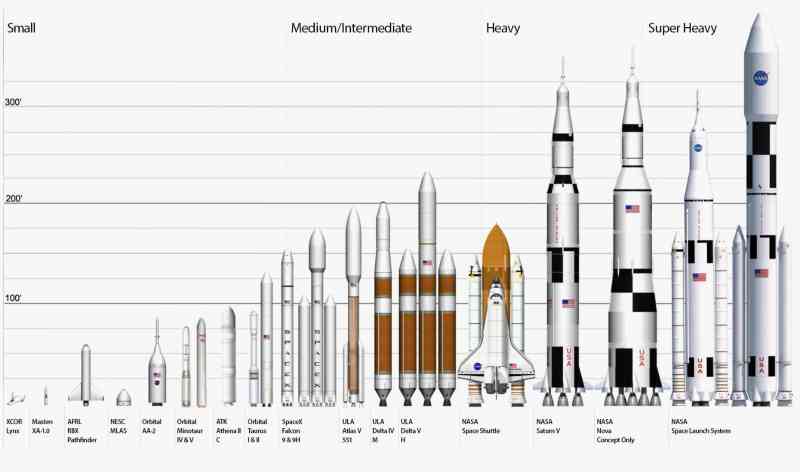
According to the requirements of Congress, the Space Launch System will be a super-heavy rocket because it will directly undertake the task of pushing human explorers to new deep space destinations and needs to be able to carry large-volume next-generation astronomical observation equipment and space science payloads. After it forms initial operational capability, it will be able to deliver 70 tons of payload into low-Earth orbit, a figure that will be increased to more than 130 tons in future models that are further developed; it will carry the "Orion multi-purpose manned spacecraft"; it will also serve as a backup launch vehicle to support the International Space Station (ISS) when the launch vehicles provided by existing commercial or international partners cannot meet the cargo and astronaut transportation needs of the International Space Station. These mission requirements, as well as the specific Design Reference Mission (DRM) and safety, affordability, and reliability quality factors (FOM) proposed by NASA, have promoted detailed technical research and resource planning, and the concept of the Space Launch System has been gradually improved during the research and development process.
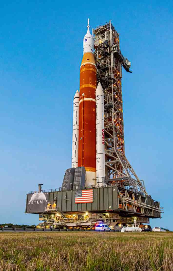
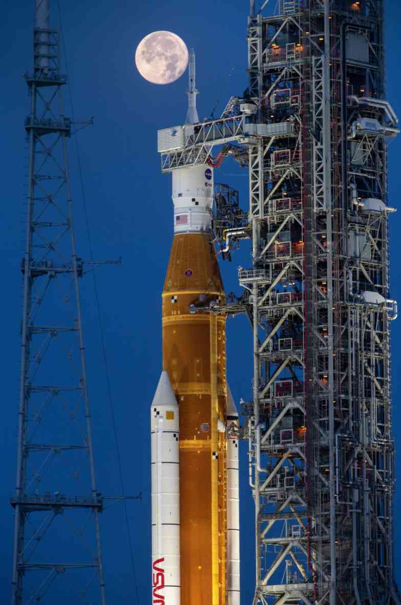
The "NASA Authorization Act of 2010" clearly mentioned that the Space Launch System launch vehicle will be a launch vehicle "inherited from the Space Shuttle", which is fully reflected in the overall design of the rocket. After a lot of preliminary research, the basic configuration of the Space Launch System that was finally finalized includes a core stage with a diameter of 8.4 meters, its storage The tanks will deliver liquid oxygen and liquid hydrogen (LOX/LH2) to the four RS-25 engines (the main engines of the Space Shuttle), leveraging the United States’ 30 years of experience with this propellant, including manufacturing facilities and launch sites, and using more than a dozen RS-25 engines in NASA’s inventory. The boosters of the Space Launch System are two extended solid rocket boosters from the Space Shuttle, and the upper stage of the rocket has many commonalities with the core stage, such as its outer diameter, material composition, subsystem components and manufacturing equipment and processes, thereby enhancing performance in terms of cost and risk control.
Another notable feature of the Space Launch System launch vehicle is that its configuration will continue to improve over time and as new technologies mature. According to NASA’s plan, the Space Launch System will have multiple different configurations, which will organically integrate the completion of short-term missions and the satisfaction of long-term indicators. The initial Space Launch System launch vehicle configuration will be called SLS Block 1, and will be divided into two types: manned and cargo, which will be enough to send at least 70 tons of payload into low-Earth orbit. In the future, the new configuration with a new upper stage and solid rocket booster will be called SLS Block 1B and Block 2. At that time, SLS Block 2 will fully meet the 130-ton low-Earth orbit capacity indicator required by Congress. The differences and connections between the different configurations of the Space Launch System launch vehicle will be discussed in detail below.
Organizational structure of the Space Launch System Project Office
It is divided into several parts, including: 1. Liquid Engine Office, responsible for the core stage RS-25 engine and upper stage engine related work;
2. Stage Office, responsible for the development of the core stage (CoreStage, CS) and the exploration upper stage (ExplorationUpper Stage, EUS);
Vehicle:
3. Booster Office, responsible for solid rocket boosters
4. Spacecraft/Payload Integration and Improvement Office, responsible for the Interim Cryogenic Propulsion Stage (ICPs) and advanced research and development projects, which will upgrade the initial SLS Block 1 launch vehicle to Block 1B and Block 2 after being put into practical application;
5. Ground Facilities Liaison Office, responsible for coordinating the integration between the Space Launch System and ground facilities systems.
Main components of the Space Launch System launch vehicle
Core stage: external fuel tank, and the gold medal power from the space shuttle
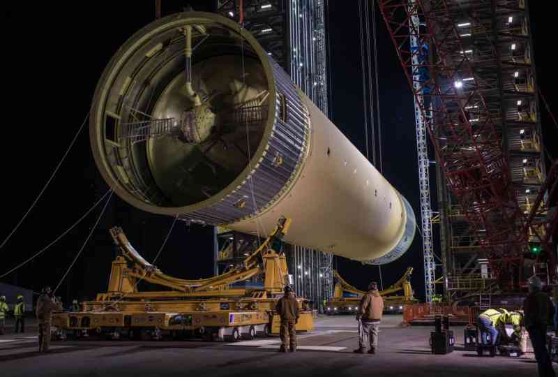
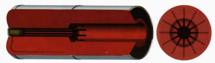
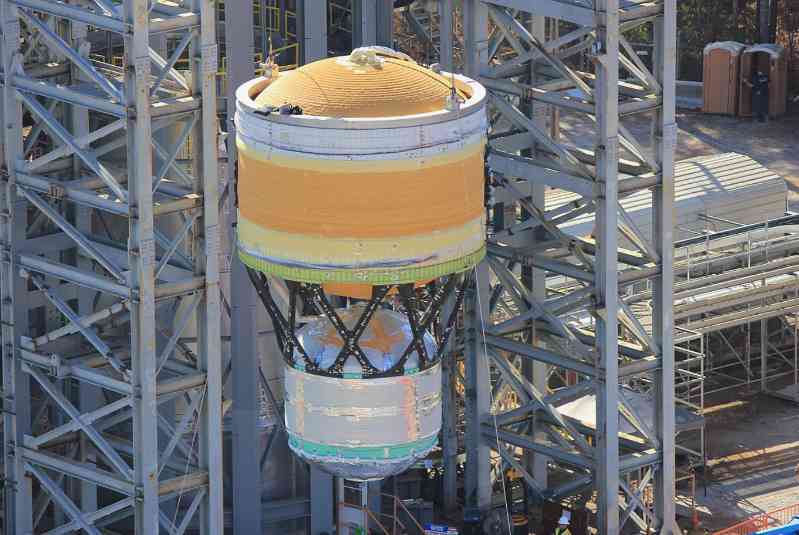
When we see the Space Launch System launch vehicle for the first time, our eyes will be attracted by its huge core stage. The core stage of the Space Launch System includes the main propulsion system (MPS) of the entire rocket, which provides about 25% of the total thrust at launch. The core stage is 65 meters long and 8.4 meters in diameter, the same diameter as the external tank (ET) of the space shuttle, but much longer than the former, and this is not without reason - for NASA, redeveloping a rocket and a matching engine from scratch is unacceptable from the perspective of cost and project progress. Therefore, the design of the core stage fuel tank of the Space Launch System is based on the improved space shuttle fuel tank. This design allows the production process to continue to use the relevant technologies, equipment and processes of the Space Shuttle Program. The core stage is manufactured at NASA’s Michoud Assembly Facility and is common to all currently planned SLS improvements to avoid the need for redesign to meet different requirements.
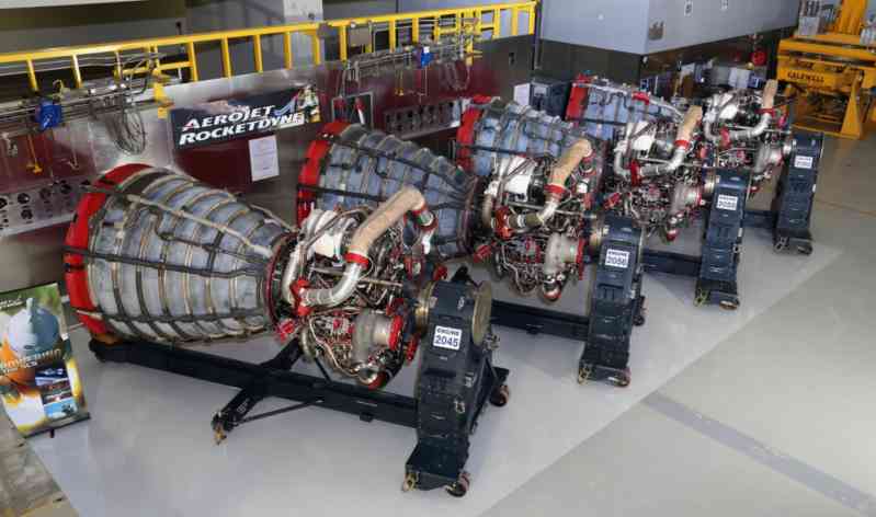
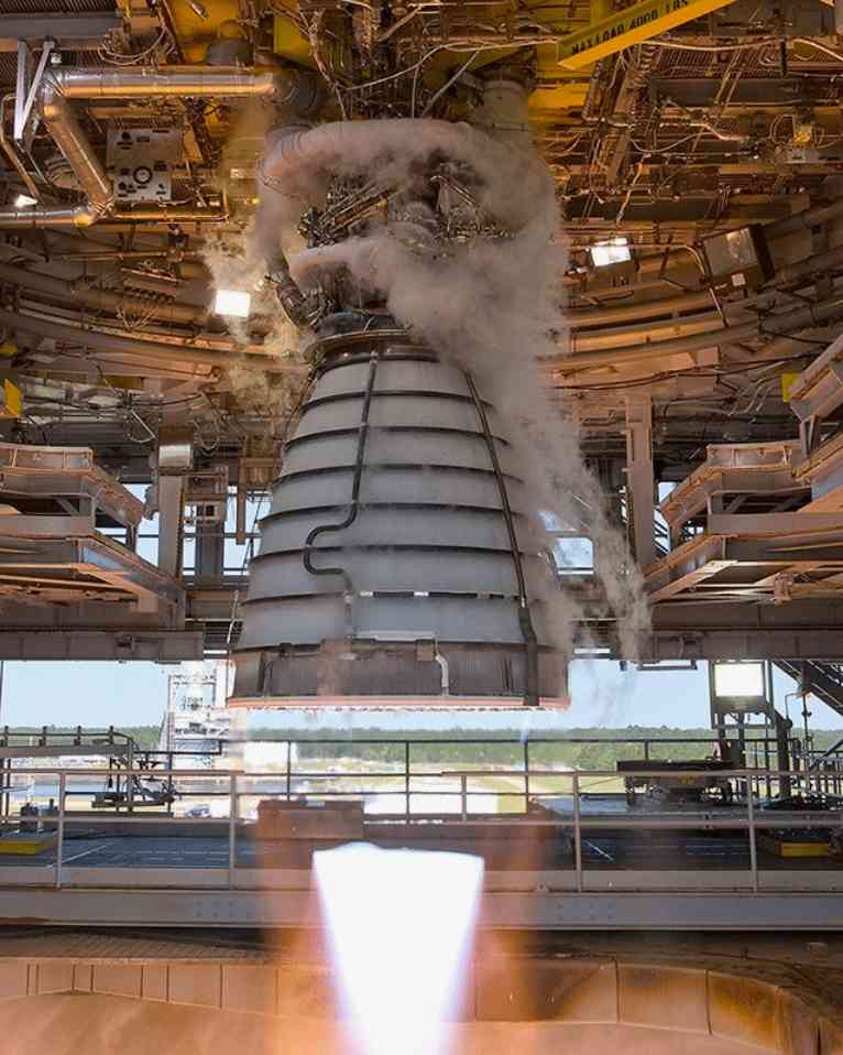
The core stage of the Space Launch System is powered by four RS-25 engines, which are designed to last 50 launches and are known for their reusability. The first four launches of the Space Launch System will use 16 RS-25D engines left over from NASA’s previous space shuttle program. To date, these engines have been modified with modern engine controllers, increased throttle limits, and enhanced thermal insulation for the high temperatures that the engine sections will experience from the side solid rocket boosters. After these launches, the Space Launch System will switch to improved RS-25 engines optimized for one-time missions by the "RS-25 Production Restart Project", which will reduce the cost of each engine by more than 30%, thereby reducing expenses.
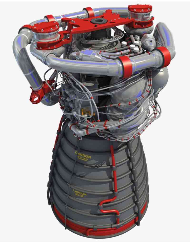
The RS-25, which was once used for the Space Shuttle and now powers the Space Launch System, is a reusable liquid hydrogen-liquid oxygen rocket engine that uses a fuel-rich staged combustion cycle and regenerative cooling. It can generate more than 232 tons of vacuum thrust, equivalent to 12 million horsepower. Its high-performance fuel and oxidizer turbopumps generate 69,000 horsepower and 25,000 horsepower respectively. The RS-25 engine is the only liquid rocket engine to date with a total operating time of more than one million seconds (reliability of 0.9996), consuming a total of more than 1.36 million cubic meters of propellant, and ensuring safe and stable operation during all 135 flights during the service of the Space Shuttle. During these flights, the engine still worked normally for about 500 seconds at 104.5% of the rated power level. All of the above data are intuitive manifestations of the excellent performance of this engine.
When the RS-25 was initially selected for the SLS, it was generally believed that the STS engine certification could be directly applied to the SLS as long as the changes in engine operating conditions and working environment were taken into account. The Liquid Engine Office analyzed the new requirements for the RS-25 engine for the SLS mission to determine whether these new requirements would affect the budget, test schedule, and engine specifications. Since there are more than ten engines in stock, it is necessary to avoid the introduction of new requirements that would cause changes in specifications and design details to affect the finished engines in stock.
Adapting the RS-25 engine to the requirements of the SLS requires verifying the engine’s compliance with the new standards without significantly affecting the budget or technical details. As a mature engine, most of the technical specifications and design and production standards of the RS-25 have been finalized and passed the accounting according to the principle of "inherited exemption", but new equipment added during the adaptation process of the SLS needs to be strictly reviewed in accordance with the design and production standards of the SLS. At the start of the adaptation effort, the baseline assumption was that, unless proven otherwise, the RS-25 would face better operating conditions when integrated with the SLS than when originally assembled on the Space Shuttle. The Main Engine-Orbiter Interface Control Document (ICD) from the Space Shuttle program was used as the starting point for designing the RS-25-SLS core stage interface. Other existing documents used in the SLS program included the Shuttle Main Engine Operations and Maintenance Requirements and Specifications document (OMRSD), which provided guidance for ground operations, and the Launch Clearance Criteria (LCC), which provided guidance for pre-launch operations.
The use of the inherited OMRSD and LCC has led to another aspect of the adjustment of the requirements for the operation and support of the engine and rocket system. This is mainly because the existing documents and standards are based on the space shuttle. In the new project, many operating procedures will need to be re-determined to meet the needs of supporting the SLS rocket to complete the mission.
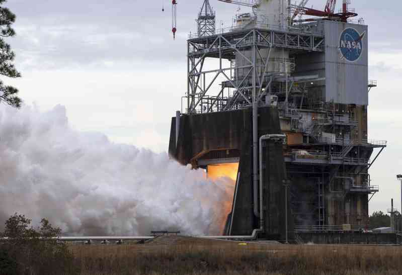
In order to successfully apply RS-25 to the space launch system, NASA has launched the "RS-25 Adaptation Program", which focuses on verifying the performance and other indicators of the improved RS-25 engine and developing a new engine controller (Engine Controller Unit, ECU) to effectively operate the engine under the operating conditions of the space launch system. To this end, the program includes a comprehensive static ignition test program, using two engines for development and two for actual flight. These engines will be tested under a series of operating conditions to prove their ability to meet mission requirements and verify the actual performance of six sets of control equipment. The plan requires that one development engine be started at least seven times and run for 3,500 seconds, two actual flight engines be started at least once and run for 500 seconds, and the second development engine be started at least nine times and run for 4,500 seconds. For most of the static fire test process, the engine will maintain a power level of 109%, which is the emergency power level specified in the space shuttle program, but the Space Launch System plans to use 109% power as the nominal power level. In the test program, according to the requirements of different test objectives, the performance of the engine at different powers will also be verified, including 104.5%, 100%, 95% and 80% of the rated power. From January 2015 to October 2017, NASA’s Stennis Space Center (SSC) conducted 18 static fire tests adapted for the Space Launch System. These engines were tested under sea level conditions on the A-1 test stand, accumulating nearly 9,000 seconds of test time on development and actual flight engines.
Although RS-25 is actually a very mature engine, it is integrated into a launch vehicle with different requirements, payloads, environment and operating procedures than those used by the space shuttle. During the integration process, engineers found and solved many problems:
1. The liquid oxygen inlet pressure is large. The space launch system uses more than the space shuttle, and the tank capacity is larger, resulting in a significant increase in length, exceeding the space shuttle external fuel tank. Therefore, it is necessary to increase the length of the oxidizer pipeline, which causes the increased pressure head to produce a higher than the nominal liquid oxygen inlet pressure in the past. This poses a risk to the normal start of the engine, which may cause the fuel/oxidizer mixture ratio in the preburner to deviate from the ideal value, thereby damaging the preburner. In addition, the acceleration of the rocket during flight will produce a gradual increase in inlet pressure, which may cause a transient water hammer effect after the main engine is shut down during flight, and there is a risk of damaging the pipeline structure.
2. Low liquid oxygen inlet temperature. Like the previous problem, this problem will also affect the normal start of the engine. This problem can be alleviated by installing an electric heater on the liquid oxygen pipeline.
3. Changes in the environment in which the engine is located. On the space shuttle, the lower edge of the RS-25 nozzle is located about 4 meters above the lower edge of the solid rocket booster nozzle. However, on the space launch system, the lower edges of the nozzles of both are almost on the same plane. This leads to an increase in the radiant heat load from the booster wake on the core stage engine nozzle, and it is necessary to lay injection molded ablative insulation material on the side of the nozzle facing the booster.
4. Booster Separation Motor (BSM) wake effect. In addition to the heat flux generated by the solid rocket booster, the wake of the booster separation motor installed on the rear skirt of the booster and the impact of debris from the nozzle cover also pose a risk to the engine. The R&D team ensured that the main engine would not be affected by ensuring that the thickness of the ablative insulation layer was sufficient to cope with the wake and installing a stopper for the nozzle cover.
5. Core Auxiliary Power Unit (CAPU). On the space shuttle, the hydraulic system was powered by an auxiliary power unit (APU) that used hydrazine fuel. However, NASA emphasizes the minimum use of toxic propellants, so instead, the Space Launch System will use hydrogen diverted from the RS-25 propellant tank to drive the hydraulic system for the CAPU. After passing through the CAPU, the hydrogen exhaust is discharged through several nozzles, which are located on the tail partition of the core stage, close to the engine. In order to deal with the risk of hydrogen igniting and affecting the RS-25 nozzle, an ablative insulation layer needs to be arranged at the nozzle.
6. Thermal environment issues in the tail compartment of the core stage. Modeling and analysis of the thermodynamic environment of the tail compartment of the rocket core stage found that unexpected low temperatures may affect the accuracy of engine sensors and the fluid properties of the hydraulic system. Further analysis showed that the main factor causing the low temperature was the oxidizer feed pipeline leading to the engine through the compartment. Adding hot nitrogen purge is a mitigation measure for this problem. In addition, the team also considered adding an insulation layer to the oxidizer feed line, although this conflicts with the use of heaters to alleviate the low temperature of the liquid oxygen inlet. Although the current analysis results show that the overall temperature is acceptable without insulation, in actual applications, in order to ensure that there is no risk, some hydraulic lines will require ground-powered electric heaters before the rocket is launched.
7. Fuel discharge before launch. Before the rocket is launched, a portion of the flow needs to be discharged from both the fuel and oxidizer systems to adjust the temperature state of the engine. The exhaust flow conditions and duration required for the RS-25 engines are well established based on experience with the Space Shuttle. However, the rated flow rates of the ground facilities are not compatible with the increased flow rates caused by the additional engines on the SLS launch vehicle, which requires coordination of the engine flow requirements with upgrades to the affected ground support equipment.
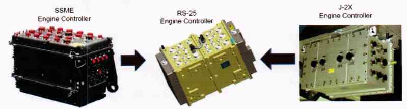
8. Update ECU - The only significant hardware component on the RS-25 engine that needs to be upgraded for integration activities is the engine controller. Its functions include: receiving and responding to commands from the rocket, providing closed-loop thrust and propellant mixture control of the engine during core stage operation by controlling the position of the adjustable propellant valve of the preburner, managing engine status (i.e., start, ignition, working, shut down, etc.), and continuously monitoring engine operating conditions. Provide data and engine health status reports to flight controllers and provide power to all engine control elements, sensors, and actuators. The ECU from the Space Shuttle era is technologically obsolete and is incompatible with the power system and data architecture of the SLS rocket. In addition, many of the parts used in the old ECU have also been discontinued. However, during the Constellation Program, a new ECU design originally developed for the J-2X upper stage engine could be retrofitted into a suitable replacement. Using the J-2X ECU design as a starting point greatly saves time and resources compared to "designing from scratch."
The A-1 test stand at NASA’s Stennis Space Center (SSC) was selected as the location for all RS-25 adaptation work tests. The test stand is capable of static ignition tests of rocket stages up to 10 meters in diameter. The test stand can provide cryogenic liquids, hydrogen, inert gases, industrial water and electricity required for test operations, and undertakes The huge heat flow and thrust during the load ignition test. During the Constellation program, the test bench was used to test the J-2X engine. In order to carry out RS-25 adaptation tests, the test bench had to be significantly modified. The test team replaced all propellant feed lines and other operating lines in accordance with RS-25 requirements. The thrust measurement system was also modified to adapt to the RS-25 engine and higher thrust loads. During preparation, all equipment lines were thoroughly inspected and passed the on-site evaluation.
From January 2015 to January 2018 , a total of 18 engine static ignition tests were conducted as part of the adaptation test. Two of these tests were engine acceptance tests, testing the flight engine. 16 tests were conducted on two development engines, and the reason for using two engines was to take into account the limitations of the service life of the components of a single engine. All engine controllers were certified on the same engine to eliminate potential differences caused by different engine hardware. By the end of the test series, most of the cumulative ignition time was carried out at 109% and 80% of the rated power levels, because the engine will mainly operate at these power levels during flight.
Throughout the test process, the test team obtained a large amount of first-hand data covering all aspects of the engine’s operation. This data was provided to the digital modelers, allowing their engine digital models to be improved in a timely manner to guide subsequent test plans. An important result of this project is the ability to adjust the prediction of engine performance indicators using models based on the latest thermal test data. These results will be applied to the subsequent RS-25 restart production project
Solid rocket boosters, and the Booster Life Extension (BOLE) project
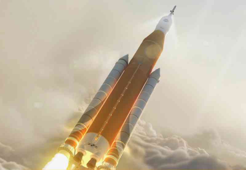
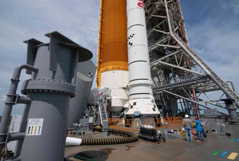
The core stage of the Space Launch System has four powerful RS-25 engines, but when the rocket takes off, the thrust provided by these four engines only accounts for 1/4 of the total takeoff thrust. This shows that the main contributors to the takeoff thrust are the two solid rocket boosters located on both sides of the core stage, which are inconspicuous compared to the huge core tank. On SLS Block 1/1B, these two boosters will be the redesigned five-segment solid rocket boosters (Redesigned Solid Rocket Motor-VRSRMV), whose technical basis comes from the space shuttle project and is used in the "Ares" series of launch vehicles in the "Constellation" program. On SLS Block 2, the planned advanced booster (Advanced Booster, AB) will replace the RSRMV.
The SLS Block 1/1B booster is 54 meters high, more than 17 stories high, 3.6 meters in diameter, and weighs 725 tons per unit. As the largest solid rocket booster ever used for flight, it generates a peak vacuum thrust of 1,633 tons and burns for about 126 seconds. Although this booster looks almost identical to the space shuttle booster, it has been improved in several aspects compared to the earliest space shuttle boosters.
The five-segment solid rocket booster of the Space Launch System is closely related to the four-segment booster of the Space Shuttle. As part of NASA’s Space Shuttle program, the booster has undergone some key design and process improvements in the Space Launch System project to meet the performance requirements of the Space Launch System mission, enhance safety, reliability and production efficiency, and reduce overall costs. From the appearance, the most obvious difference is that the booster of the Space Launch System is longer than the Space Shuttle booster, from a 4.5-section structure to a 5-section structure. The additional propellant provides a longer working time and a higher total impulse. In the mission of the Space Launch System, since the recovery equipment will occupy a part of the transportation capacity and affect the payload of the rocket, NASA has no plan to recover the booster, so the parachutes and other equipment related to the recovery have been removed. The new booster uses new avionics, new propellant particles, asbestos-free insulation shell, redesigned nozzle, simplified manufacturing process and new detection technology. These new materials and processes provide better performance, safety and affordability, but also bring new challenges to the R&D team.
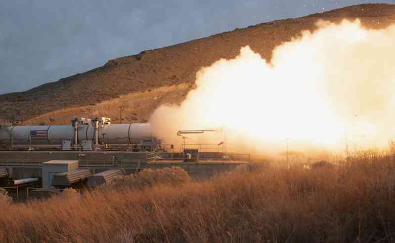
The team of OrbitalATK, which is responsible for the development of solid rocket boosters, successfully conducted two full-scale test runs (QM-1/2) in early 2015 and July 2016, and comprehensively tested and verified the various performance parameters and performance of multiple full-scale boosters. On March 11, 2015, Orbita1ATK conducted the QM-1 test in Cape Cod, Utah. QM-1 has 75 identification test targets, 9 demonstration test targets and 18 development test targets, and was tested at 33°C. Strict evaluation standards and more than 530 instruments of various types were used to ensure that the test was foolproof.
Test objectives focused on the SLS program requirements for overall engine performance, thrust vector control system performance, thermal insulation, structural integrity, joint sealing, and nozzle ablation resistance. The five-segment SRB internal thermal insulation system has been redesigned and optimized since the Space Shuttle program due to the obsolescence of asbestos materials and the need for more environmentally friendly materials, making the QM-1 test segment the best insulated booster segment ever produced.
The SLS boosters utilize many proven components from the Space Shuttle era. Some components were taken directly from the Space Shuttle program inventory, some were slightly modified from older components, and others were significantly modified or replaced.
A prime example of an unmodified component is the engine safe and arm (S&A). The engine segment shell is also used directly without any modification, except for the processing of reinforcement ribs in the rear section. The main structure of the booster front section assembly remains basically unchanged, including the nose cone, cone and front skirt. The metal structure and charge of the engine igniter are the same as those used in the space shuttle program. The booster tail skirt structure and thrust vector control system also maintain the original design.
Other parts have been modified for the conditions of the Space Launch System project. Although the engine igniter has not changed fundamentally, a layer of silica-filled nitrile rubber (SF-NBR) shear layer has been added to the inner wall of the critical area, thereby improving the thermal insulation structure. The solid propellant used in the QM-1 test is a composite solid propellant formula composed of polybutadiene-acrylonitrile-acrylic acid terpolymer adhesive, epoxy curing agent ammonium perchlorate oxidizer, aluminum powder fuel and a small amount of iron oxide burning rate catalyst. Such a formula reduces the ablation rate and is more suitable for the five-stage booster. The structure of the booster rear shell has been modified for the SLS rocket. The column section in the rear section that supports the connection with the shuttle external fuel tank has been moved back by changing the position of the reinforcement ribs to adapt to the structure of the SLS rocket. The RSRMV propellant charge adopts a 12-fin star design, while the 11-fin design is used in the space shuttle project. The front of the charge has a 12-fin star area, which gradually transitions to a central perforated structure at the rear of the segment. In addition, the size of these fins is longer than that of the space shuttle booster. In addition, the O-rings used for sealing have been improved from the old model on the space shuttle to improve performance and simplify the structure.
In addition, some parts are completely new designs, including the booster nozzle and the shell insulation layer, which have been completely redesigned for SLS. The QM-1 test booster head pressure data will be used to select one of the two candidate designs tested on QM-1 as a new flight pressure sensor to replace the old model on the space shuttle booster. The booster’s system components, piping, and emergency shutdown system were all designed based on the space shuttle design, with major modifications and a completely new design. In addition, the booster’s avionics system was also completely redesigned.
Although a lot of improvements have been made, the space for further improvement of the SLS Block 1/1B booster is still relatively limited due to the technical level of the space shuttle booster as the basis for research and development. Moreover, NASA’s booster parts inventory can only support 8 flights, and a large number of parts produced during the space shuttle project have been discontinued. Obviously, whether it is to continue to maintain the normal launch of the SLS launch vehicle after the inventory is exhausted, or to achieve the expected ultimate goal of 130 tons of low-Earth orbit capacity, the development of a new booster is imminent and must be launched. To this end, NASA has launched the Booster Generation Life Extension (BOLE) project and temporarily named the planned new generation of boosters "Advanced Booster".
The booster replacement and life extension project is led by NASA and developed by Northrop Grumman’s Space Systems Division. It has made drastic improvements and optimizations to existing solid rocket boosters, and has superior performance to existing boosters in all aspects. Compared with the current SLS boosters, the improvements of advanced boosters are mainly concentrated in the following aspects:
(A) Improvements in solid rocket design
1. The use of composite shells and new joints using advanced composite fiber technology provides a weight reduction of up to 30% and better joint sealing, and greatly improves production economy compared to traditional metal segments;
2. Improved industrial-grade hydroxy-terminated polybutadiene (HTPB) propellant can allow for higher strain levels caused by the use of composite segments, and no longer requires the special polymerization form of traditional boosters;
3. The use of new elastic insulation materials is lower in cost and more compatible with new propellants;
4. The nozzle is specially optimized for new propellants and has stronger performance.
(B) Improvements in booster structure and thrust vector control
1. Improvements in booster structure to simplify production processes, replace old technologies and be compatible with solid rockets, including integrated nose cone and front cone sections, front skirt with optimized structural strength, simplified system component piping, new booster/core stage connection-separation mechanism, and easier-to-produce rear skirt;
2. Electronic thrust vector control system, replacing the control mechanism driven by toxic materials on the old booster, greatly simplifying ground operation and handling procedures.
The research and development of advanced boosters is still progressing steadily. The research and development of many components including the shell, nozzle, thrust vector control system and ground servo equipment has made significant progress. After the application of the new booster, the overload analysis during the launch of the space launch system has also been completed, and the results will be used to improve the propellant charge structure. According to the progress expected by the R&D team, by the ninth launch of the Space Launch System, the advanced booster will be combined with the Space Launch System core stage equipped with a new upper stage to form the planned ultimate form SLS Block 2.
Analysis shows that for lunar missions, the advanced booster provides at least 3 tons of additional Earth-Moon transfer orbit capacity, and this increase will be more significant when traveling to more distant destinations such as Mars, and even Jupiter and Saturn. For missions directly to Jupiter, the advanced booster can provide a 10% capacity increase, and for Saturn missions, this number is even increased to 20%, which is a huge advantage for deep space missions where weight is a must.
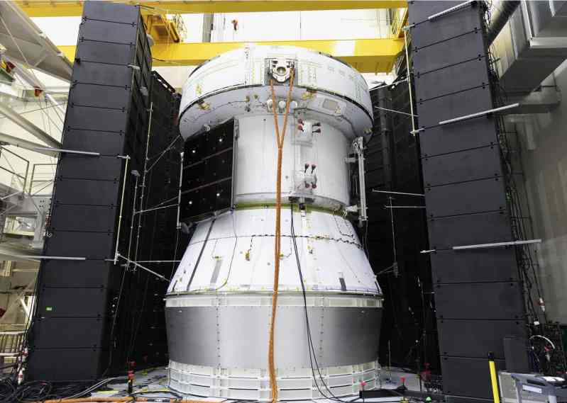
Upper stage: from Interim Cryogenic Propulsion Stage (ICPS) to Expeditionary Upper Stage (EUS)
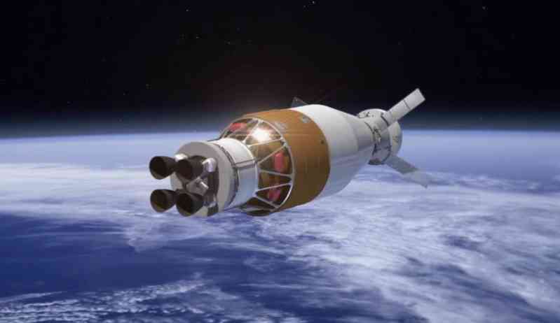
The upper stage of the Space Launch System also has multiple versions of different designs. In the earliest design stage, the Space Launch System will use a 5-meter diameter interim upper stage, and in full space, the launch system upper stage will use the J-2X engine that was planned to be used by the Ares V launch vehicle. This engine is an upgraded version of the J-2 upper stage engine developed for the Saturn V launch vehicle. It has the ability to be restarted multiple times and can generate about 133 tons of thrust to send payloads from low-Earth orbit to deep space. However, with the design changes, this plan was abandoned and replaced by the Interim Cryogenic Propulsion Stage (ICPS) and the further Exploration Upper Stage (EUS).
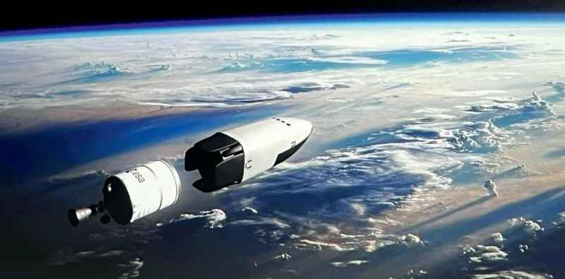
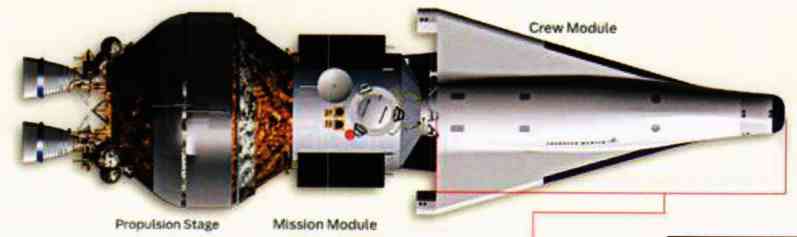
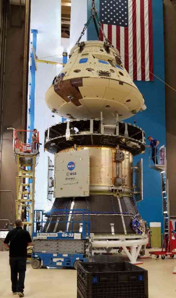
The name of the Interim Cryogenic Propulsion Stage has clearly pointed out its mission, which is to temporarily support the launch mission of the Space Launch System before the new generation of upper stages are put into use. The interstage and upper stage of SLS Block 1 and the payload together constitute the spacecraft/payload assembly (Integrated Spacecraft/Payload Element, ISPE). The spacecraft/payload combination of the manned SLS Block 1 consists of the Launch Vehicle Stage Adapter (LVSA), the ICPS upper stage and the Orion Stage Adapter (OSA). During the Orion mission, the stage adapter can be equipped with a secondary payload (SPL) as needed. For the cargo SLS Block 1 spacecraft/payload combination, the stage adapter will be replaced with a 5-meter-diameter payload adapter and payload fairing, which are already mature in technology. After entering space, the power to continue to propel the SLS Block 1 payload will be provided by the ICPS upper stage, which is derived from the existing United Launch Alliance (ULA) Delta rocket cryogenic second stage (DCSS). This 5.1-meter diameter upper stage has been flown more than 20 times on the Delta IV "Evolved Expendable Launch Vehicle (EELV)" as a pilot launch vehicle. A Rocketdyne RL-10 liquid hydrogen and liquid oxygen engine powers the stage, with a mission life of approximately 8 hours. It is connected to the core stage of the Space Launch System via a launch vehicle adapter. The front skirt of the ICPS upper stage is connected to the spacecraft through the "Orion" spacecraft adapter during manned missions and provides an interface for connecting to the 5-meter payload adapter and fairing for cargo missions.
In November 2016, engineers loaded the test ICPS upper stage onto a nearly 20-meter-tall structural test stand at Marshall Space Flight Center as part of Integrated Structural Testing (IST). The test objects included the launch vehicle stage adapter, frangible joint assembly, ICPS upper stage, Orion spacecraft adapter, and Orion spacecraft and core stage simulators. In 2017, the experimental team tested the upper stage in 50 different situations to ensure that it can withstand the challenges of the harsh environment during launch.
United Launch Alliance has completed the design and construction of the ICPS upper stage for the first Space Launch System mission in Decatur, Arizona, and delivered it to Cape Canaveral Air Force Station for integration in February 2017. This is the first Space Launch System subsystem to go to Florida for final processing and testing before being transferred to the ground facilities at Kennedy Space Center.
When the first ICPS upper stage had not yet entered space, the research and development of its replacement, the Expedition Upper Stage (EUS), was already in full swing. Compared with the 98.1-meter height of SLS Block 1, the increased length of the EUS upper stage has increased the height of the manned SLS Block 1B by more than ten meters, reaching 111 meters, and the cargo type is also 99.3 meters high. The EUS upper stage of SLS Block 1B will provide the payload with ascent/orbit circularization and space transfer capabilities. It uses a liquid hydrogen tank with a diameter of 8.4 meters and a liquid oxygen tank with a diameter of 5.5 meters. Four RL-10 liquid hydrogen and liquid oxygen engines will provide power for the upper stage, and the onboard battery will provide power for the upper stage, while the passive thermal control system will minimize the boiling of cryogenic propellants throughout the life of the EUS upper stage. The mechanical interface of the Space Launch System is connected to the EUS upper stage through an interstage with a diameter of 8.4 meters, and the top interface of the EUS is also 8.4 meters in diameter to maximize the universal design. The spacecraft/payload assembly of the manned SLS Block 1B consists of the Space Launch System Payload Adapter (PLA) and the Universal Spacecraft Adapter (USA), and can accommodate cargo and secondary payloads on the payload adapter as needed. The top of the USA is the standard interface of the "Orion" spacecraft stage adapter. The spacecraft/payload assembly of the cargo SLS Block 1B uses a payload adapter and a payload fairing to accommodate primary/secondary payloads, and will be able to carry large payloads such as living cabins, landers or other large cargo.
NASA began in early 2017 and completed the preliminary design review and critical design review of the EUS upper stage. The review paved the way for preparations at the beginning of research and development. The upper stage will be manufactured at the Michoud Assembly Facility and undergo a series of tests at the Stennis Space Center and Marshall Space Flight Center using the same test stands, welding tools, structural test facilities and staging test stands used to build and test the core stage. In 2016, NASA and Rocketdyne signed a contract to produce 10 RL-10C-3 engines for the second and third Space Launch System launch missions, as well as two spare engines.
Other early development work for SLS Block 1B included wind tunnel testing at Langley Research Center, which focused on flight from transonic to supersonic speeds to verify the accuracy of computer models. During this period, additional tests were conducted to examine the impact of vibrations during launch on the cargo version of SLS Block 1B. Further testing was completed in 2017, including wind tunnel simulations of transonic oscillations and booster separation of the manned SLS Block 1B at key points in the launch process. Since this phenomenon is difficult to accurately simulate in computer modeling predictions, on-site observation in wind tunnel tests is particularly important. Wind tunnel testing at Ames Research Center evaluated the performance of SLS Block 1B during ascent in the transonic segment, including instructions programmed into the flight computer for guidance and control. As of the time of writing this article, it is certain that the development of the EUS upper stage is progressing gradually; but the overall delay in the progress of the Space Launch System project may make the debut of this type of upper stage later than expected.
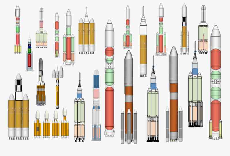
Brief description of the evolving configurations of the Space Launch System
In order to quickly form initial operational capabilities and reduce the difficulty of research and development, the Space Launch System adopts a "small steps and fast running" development model, setting up multiple different configurations to smoothly move from meeting the needs of current missions to supporting larger-scale long-term missions. Therefore, in order to give readers a more intuitive understanding of the many configurations of the SLS launch vehicle, the following will compare the similarities and differences of all the Space Launch System configurations currently planned by NASA, and summarize the characteristics of each configuration.
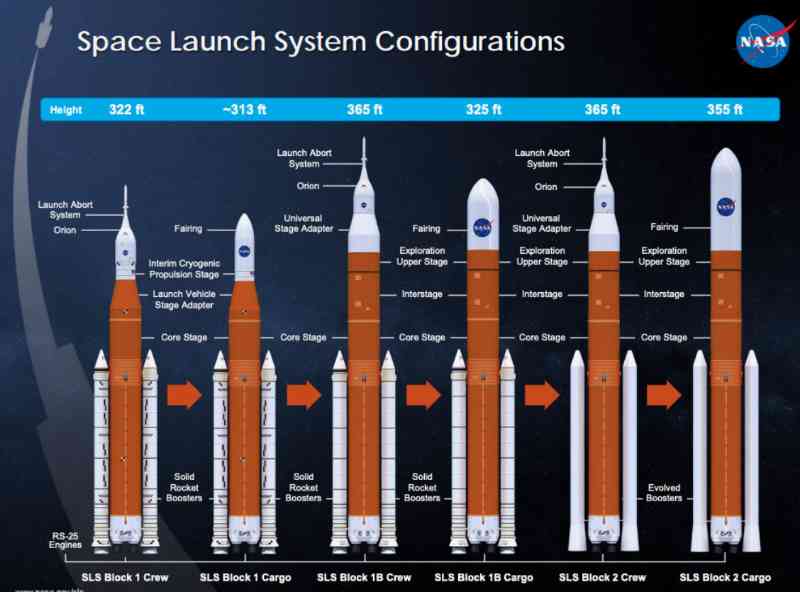
SLS Block 1--This is the basic form of the space launch system, using an 8.4-meter core stage, solid rocket boosters from the space shuttle and a 5-meter ICPS upper stage. The upper stage is directly adapted to the "Orion" spacecraft to perform manned missions, with a low-Earth orbit capacity of 95 tons and a 27-ton Earth-Moon transfer orbit capacity; SLS Block 1 cargo type--Based on Block 1, it is converted into a cargo-type space launch system, with a temporary cryogenic propulsion stage connected to a payload adapter and fairing to perform cargo missions, with a low-Earth orbit capacity of 95 tons and a 27-ton Earth-Moon transfer orbit capacity;
SLS Block 1B manned type--In Block 1, the temporary cryogenic propulsion stage is replaced with an expeditionary upper stage with a diameter of 8.4 meters, and a universal staging adapter is installed on the top of the upper stage, outside the payload adapter, which can carry the "Orion" spacecraft and smaller cargo payloads at the same time, with a low-Earth orbit capacity of 105 tons and a Earth-Moon transfer orbit capacity of 40 tons;
SLS Block 1B cargo type--Based on the manned Block 1B, the universal staging adapter is removed and a payload fairing with a diameter of 8.4 meters is installed, which is enough to transport large-sized cargo, with a low-Earth orbit capacity of 105 tons and a Earth-Moon transfer orbit capacity of 40 tons;
SLS Block 2 manned model - the final manned model of the space launch system, which is equipped with advanced boosters based on the manned SLS Block 1B, with a low-Earth orbit capacity of 130 tons and a Earth-Moon transfer orbit capacity of 45 tons; SLS Block 2 cargo model - the final cargo model of the space launch system, which is equipped with advanced boosters based on the cargo SLS Block 1B, with a low-Earth orbit capacity of 130 tons and a Earth-Moon transfer orbit capacity of 45 tons.
The difficult Artemis 1 mission
The Artemis 1 mission is the first major mission of the entire Artemis program. The mission was originally named Exploration Mission-1 (EM-1) and was planned in 2012. It was originally planned to be launched in 2017, the first launch of the space launch system and the second unmanned flight of the "Orion" spacecraft, which will fly around the moon for 7 days in this mission. However, in 2013, NASA required the design of the Orion spacecraft to be changed, and the European Space Agency developed the service module of the Orion. Due to the design changes, the Exploration Mission-1 was inevitably delayed. In July 2014, NASA announced that the first flight of the Space Launch System was postponed to November 2018. In April 2017, the mission was postponed to 2019, and then postponed to 2021.
On June 12, 2020, with the solid rocket booster of the first Space Launch System launch vehicle transported from Utah to Florida by rail, the launch preparations for the Artemis 1 mission at the Kennedy Space Center officially began. NASA and ground system contractors officially began assembly of the first Space Launch System in the Assembly Building on November 23. Assembly work was suspended due to the postponement of the test of the Space Launch System core stage at the Stennis Space Center, and then resumed on January 7, 2021. On March 3, the two solid rocket boosters were assembled on the SLS mobile launch pad. On April 27, the Space Launch System rocket core stage (CS-1) for this mission arrived at the launch site by the Pegasus barge after completing the ignition test and was moved to the lower level of the rocket assembly building for refurbishment and assembly preparation. On June 12, the core stage and booster were assembled. Ten days later, the stage adapter (LVSA) was installed on the rocket. Subsequently, the Interim Cryogenic Propulsion Stage (ICPS) was installed on July 6. After completing the umbilical arm retraction test and integrated modal test, the Orion spacecraft carrying out the Artemis mission completed the combination with the Space Launch System rocket on October 8, 2021, and the escape tower and fairing were subsequently installed. The Space Launch System and the Orion spacecraft combination for the Artemis 1 mission completed all assembly work on October 21, 2021. However, during the subsequent integrated test and inspection, one of the four RS-25 engines on the first stage of the Space Launch System rocket failed, and it took a long time to replace it. On March 17, 2022, the Space Launch System launch vehicle and the Orion spacecraft carrying out the Artemis 1 mission were pushed out of the assembly building and headed to the LC-39B launch pad to start the first wet dress rehearsal (WDR) test. However, due to problems with the pressurization system, the first wet dress rehearsal originally planned for April 3 was cancelled. Then, during the second test on April 4, a problem occurred with the exhaust valve while filling the Space Launch System rocket with propellant, and the rocket’s wet rehearsal was again aborted.
During the preparations for the third wet rehearsal attempt, the helium check valve on the temporary cryogenic propulsion stage was stuck by a piece of rubber from the launch pad umbilical arm, which stopped the propellant filling of the temporary cryogenic propulsion stage, and the check valve needed to be returned to the assembly building for replacement. The propellant filling of the first stage of the Space Launch System rocket was not smooth. The liquid oxygen propellant was successfully filled, but during the liquid hydrogen propellant filling, a leak was found on the umbilical plate of the bottom service mast connected to the bottom of the rocket, causing the wet rehearsal to end early again.
Based on the above exposed problems, NASA pushed the Space Launch System rocket back to the assembly building for repairs and improvements on April 26, 2022, and then the rocket went to the LC-39B launch pad for the second time on June 6 to complete the wet rehearsal that had been terminated due to various failures.
In the fourth wet rehearsal attempt on June 20, the Space Launch System rocket successfully completed the filling of two-stage propellants, but due to the rapid disconnection of the umbilical cord of the bottom service mast, a hydrogen leak occurred at the connection. The wet rehearsal stopped automatically at T-29 seconds (originally planned to be carried out to T-9.3 seconds), but NASA still announced that the wet rehearsal had completed almost all the planned test goals and announced that the wet rehearsal activities were completed. Subsequently, the Space Launch System rocket was pushed back to the assembly building on July 2, 2022 for final maintenance and launch preparations, and two launch windows were determined on August 29 and September 5, 2022.
At midnight on August 29, 2022, the Space Launch System rocket standing on the LC-39B launch pad waited for the first launch window. However, when the scheduled launch time gradually approached, the rocket encountered a series of problems. Signs of a hydrogen leak were detected in the aft service mast area at the bottom of the rocket’s core stage, causing the propellant filling work to be suspended. At the same time, cracks appeared on the insulating foam connecting the joints between the first-stage liquid hydrogen propellant tank and the liquid oxygen propellant tank, and there was a communication delay of about 11 minutes between the Space Launch System launch vehicle and the "Orion spacecraft" and the ground control station. The most fatal thing was that the temperature of the No. 3 engine of the four RS-25 engines in the first stage of the rocket exceeded the maximum temperature limit allowed for the launch (later proved to be a temperature sensor failure), making the launch procedure impossible, and NASA finally gave up this launch window.
After the failure of the first launch attempt, NASA chose September 3 at 14:17 (Eastern Time)/21:10 (UTC) as the second launch window for the Space Launch System rocket, which will last about 2 hours. However, during the propellant filling process before the launch, the liquid hydrogen propellant filling pipeline connecting the rocket and the mobile launch platform leaked. Since the fault could not be eliminated, this launch window was abandoned again.
After two failed launch attempts, NASA scheduled the third maiden flight of the Space Launch System rocket for September 27, 2022. However, during the pre-launch test, a propellant leak was detected again during the liquid hydrogen propellant filling on September 21, and the leak area was basically the same as before. The sudden tropical storm "Ian" further disrupted the first flight plan of the Space Launch System rocket. Due to the extremely strong intensity of this tropical storm, it is very likely to affect the Space Launch System rocket still on the launch pad or even damage the rocket. In the end, NASA made a decision on September 26, 2022 to abandon the launch window on September 27 and push the Space Launch System rocket back to the assembly building again.
With the Space Launch System rocket returning to the assembly building on September 27, the first flight launch attempt, which lasted about one month, came to an end. It is worth mentioning that shortly after the Space Launch System rocket returned to the Assembly Building, a small fire broke out in the electrical panel on the wall of the Assembly Building, and the personnel in the building were evacuated, but it did not affect the rocket.
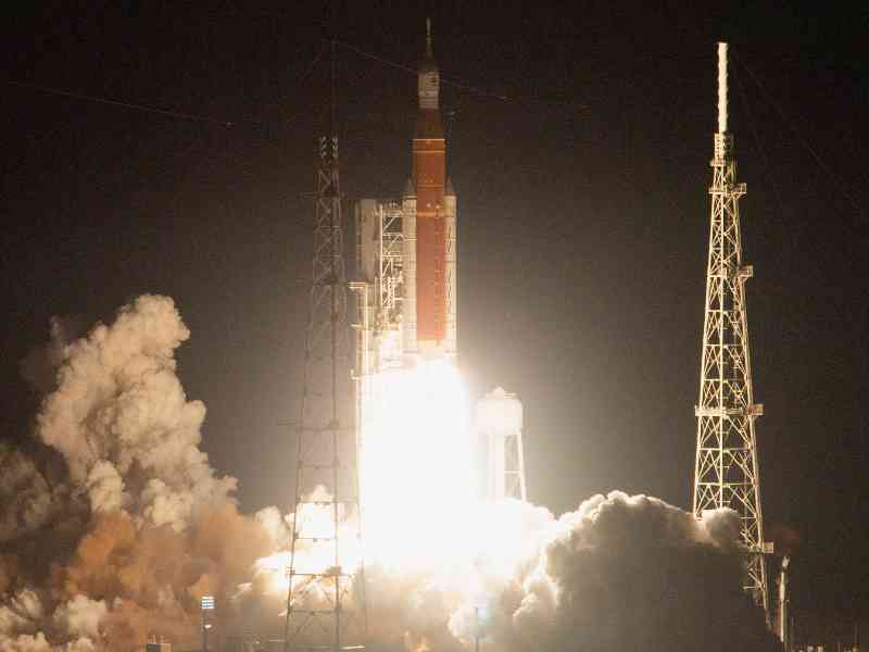
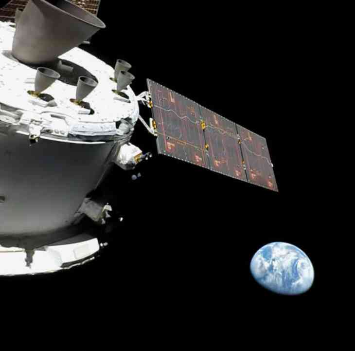
On November 4, 2022, the Space Launch System rocket was pushed out of the Assembly Building for the fourth time and headed for the LC-39B launch pad. Due to the landfall of Hurricane Nicole in Florida, the launch window on November 14 was canceled, and the rocket faced the hurricane on the launch pad. Due to the maximum wind speed of Nicole during the transit, which reached 141 kilometers per hour, exceeding the maximum score (136 kilometers per hour) that the Space Launch System rocket design can withstand, this caused minor damage to the rocket, causing the rocket to loosen the umbilical cord connector with the service mast and the insulation material of the Orion spacecraft, but fortunately it did not affect the subsequent launch plan on the 16th. On November 15, 2022, the Artemis 1 mission management team began to fully prepare for the launch, and the propellant filling procedure began at 3:30 pm Eastern Time. After experiencing a liquid hydrogen propellant leak (resolved by technicians manually tightening the sealing nut) and the loss of key radar system data at the Space Force Eastern Range, which provides tracking and telemetry support for the Space Launch System rocket (network switch failure, needing to be replaced), the Space Launch System rocket carrying the "Orion" spacecraft was launched from the LC-39B launch pad at the Kennedy Space Center at 1:47:44 a.m. Eastern Standard Time (6:47:44 UTC). After the booster and core stage were successfully separated, the Interim Cryogenic Propulsion Stage (ICPS) and the "Orion" spacecraft successfully entered the predetermined orbit 8 minutes after launch. Subsequently, driven by the Interim Cryogenic Propulsion Stage (ICPS), the "Orion" spacecraft successfully completed the Earth-Moon transfer and rushed to the lunar orbit. After completing this unmanned lunar mission, the "Orion" spacecraft is expected to return to Earth about 25 days after launch and eventually splash down in the Pacific Ocean.
Future Outlook of the Space Launch System
There is no doubt that after completing multiple upgrades, the final technology level and carrying capacity of the Space Launch System will make a huge leap on the basis of the initial model, and will firmly sit in the first echelon of the world’s launch vehicles. For the many deep space exploration missions that NASA is preparing to carry out in the future, the Space Launch System will be an indispensable backbone to achieve these missions.
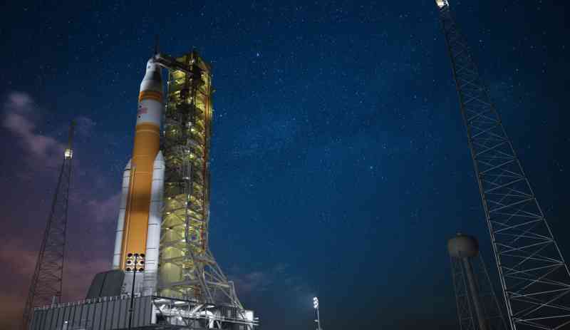
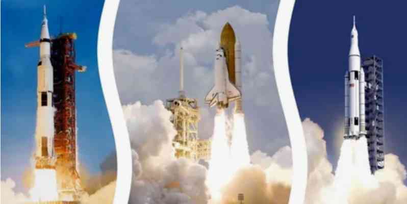
However, just like many projects that NASA has carried out, the Space Launch System project has been constantly criticized from various aspects such as progress and budget. Since the beginning of 2020, the global COVID-19 epidemic has also had a significant impact on the development progress of the Space Launch System. Today, the first Space Launch System has been quietly erected in the rocket assembly plant of the Kennedy Space Center, waiting for the day of the final launch. By then, we will hear the first roar of the next generation of the flagship launch vehicle of the US space program, more than half a century after the Saturn V withdrew from the historical stage and more than a decade after the space shuttle was fully retired. We will also hear the first thunderclap of the Artemis program, a huge project that is destined to shine in the next decade or even longer.
The "Orion" spacecraft carrying the "Artemis" ship
The Manned Exploration Vehicle (CEV) phase
The "Orion" multi-purpose manned spacecraft (Orion Multi-Purpose Crew Vehicle/Orion MPCV) originally originated from the Space Exploration Initiative (Space Exploration Initiative) proposed by President George Herbert Walker Bush in 1989. Initiative, SEL). The project included a series of ambitious plans such as building a large space station, returning to the moon and eventually landing on Mars. But after Bill Clinton took over the presidency, this ambitious plan came to nothing.
Then under the leadership of President George Walker Bush, NASA resumed planning a series of projects to land on the moon in 2004. On January 14, 2004, President Bush officially announced the next-generation manned exploration vehicle (Crew) in a speech at NASA headquarters. The Constellation project concept is a manned spacecraft that will be used for a series of manned deep space exploration missions such as landing and exploring the moon, Mars and other extraterrestrial planets. After the official launch of the Constellation program, NASA issued a request for proposals (RFP) for the manned exploration vehicle (CEV) on March 1, 2005. On June 13 of the same year, NASA selected two teams consisting of Lockheed Martin and Northrop Grumman and Boeing to further develop the manned exploration vehicle and signed a development contract of US$28 million. The two R&D teams were required to complete the complete design of the spacecraft and related subsystems by August 2006, and provide a complete plan for going to the moon and the final landing.
On August 31 of the following year, NASA announced that Lockheed Martin’s proposal had a higher level of technology and lower cost, thus defeating the Northrop Grumman/Boeing team and winning the contract to design and develop a new manned spacecraft, which was named "Orion" (because American astronaut Jeff Williams on the International Space Station accidentally revealed during a radio call to Earth that the manned exploration vehicle had been named "Orion", NASA had to announce the name in advance on August 22. The name "Orion" was used for the Apollo 16 lunar module that landed on the moon in April 1972).
Lockheed Martin’s initial proposal was a lifting body configuration similar to a small space shuttle, capable of accommodating 4 to 6 astronauts and related life support and experimental equipment. Compared with previous capsule-shaped spacecraft, this configuration of spacecraft is easier to navigate when returning to Earth at high speed. There will be two versions in the plan, one for low-Earth orbit missions and the other for manned lunar missions.
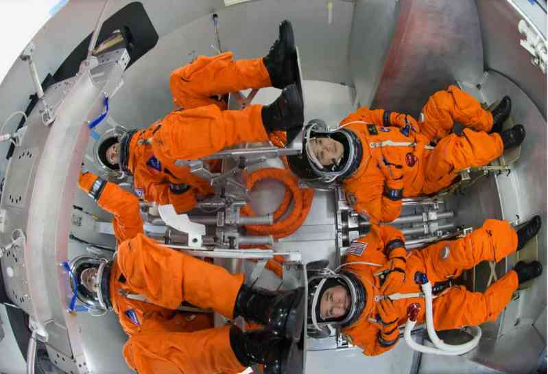
The crew module (CM) and the rescue module (RM) together constitute this lifting body structure spacecraft. During the launch, astronauts will sit in a row of two in the rescue module wrapped in a carbon-carbon reinforced (RCC) composite insulation layer, which can accommodate up to 6 astronauts. In an emergency, the rescue module will separate from the crew module and activate the escape system. The crew module is for astronauts to move around, can accommodate 4 astronauts for 5 to 7 days, and can perform extravehicular activities (EVA). After completing the mission, the crew module will land on land or water and can be reused 5 to 10 times.
The lunar mission module (MM) is installed at the bottom of the lifting body spacecraft. The lunar mission module can accommodate additional consumables and living space, and provide additional power and communication capabilities for the entire Orion spacecraft, as well as a port for docking with the Lunar Surface Access Module used for landing. At the bottom of the entire Orion spacecraft is the Trans-Earth Injection Module (TEIM), which is said to be composed of two RL-10 rocket engines developed by Pratt & Whitney Group. It was originally planned that three Evolutionary Expendable Launch Vehicles (EELVs) would launch the crew module, the lunar mission block, and the Earth-Moon Transfer Module, respectively, and fly to the moon after docking in orbit.
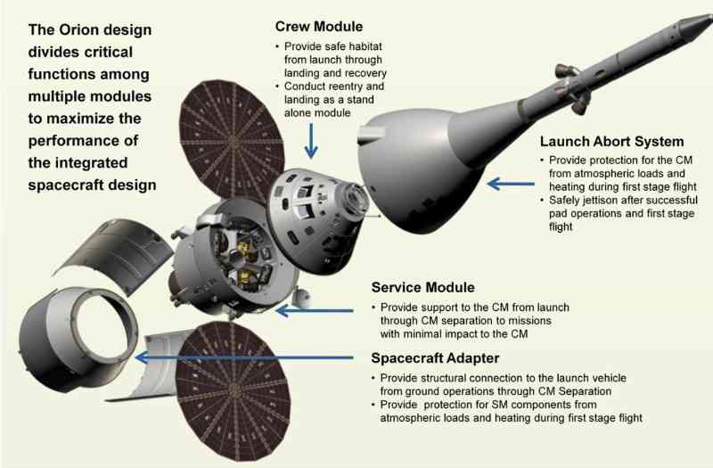
However, in the subsequent further research and review by NASA, the research plan for this configuration was cancelled and the traditional design was adopted. The crew module (CM) of the Orion spacecraft at this design stage is basically the same as the final plan, so I will not go into details here. The service module (SM) is cylindrical with a diameter of 5 meters, and a total length (including thrusters) of 4.78 meters. Made of aluminum-lithium alloy to reduce weight, it weighs about 3,600 kilograms when empty and can carry about 8,200 kilograms of propellant. It includes propulsion and energy systems, a high-gain antenna for communications, and a heat sink for dissipating heat generated in the crew cabin. The service module of this period was equipped with a circular UltraFlex solar panel similar to that of the Phoenix Mars rover. This is the first time that the United States has planned to use this type of solar panel on a manned spacecraft. This eliminates the need to install fuel cells and their related hardware (mainly hydrogen propellant tanks) that are prone to failure in the Orion spacecraft, thereby reducing the size of the spacecraft and improving its maneuverability.
Orion main engine (OMS) is a 33 kN thrust, extrusion cycle, regeneratively cooled, storable bipropellant engine manufactured by Rocketdyne. This engine is an increased thrust model of the 26 kN thrust orbital maneuvering engine on the space shuttle. The reaction control system of the service module, as the maneuvering propulsion system of the entire spacecraft (based on the R-4D four-way attitude control engine on Apollo, but it looks more like the attitude control engine on the Gemini spacecraft), will also use the extrusion cycle working principle and the same propellant. NASA believes that in the event of failure of the main engine of the service module, the engine of the reaction attitude control system of the service module will be able to serve as a backup for the main engine to send the "Orion" spacecraft into the lunar transfer orbit.
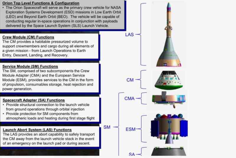
Multi-Purpose Manned Spacecraft (Orion MPCv) Phase
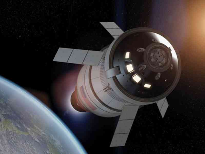
After the Obama administration drastically cut the budget of the "Constellation Program" and eventually canceled the project, the "Orion" spacecraft was renamed from the Manned Exploration Vehicle (CEV) to the Multi-Purpose Manned Spacecraft (Orion MPCv) on May 24, 2011. MPCV), and made substantial changes to the design. The new generation of "Orion" spacecraft uses the previous crew module design, but the service module is changed from Lockheed Martin’s self-designed plan to the European Service Module (ESM) manufactured by Airbus Defense and Space to reduce R&D and production costs. The new generation of "Orion" spacecraft weighs about 33,400 kg (including the escape tower) and can carry 2 to 6 astronauts. It can provide 4 astronauts with 21 days of operation in orbit, and up to 6 months with docking and resupply.
The main power of the "Orion" spacecraft comes from 1 AJ-10 engine, in addition to 8 R-4D-11 engines and 24 custom reaction engines developed by Airbus. Force Control System (RCS) engine. Although compatible with other launch vehicles, the Orion spacecraft is still primarily designed to be launched by the Space Launch System (SLS) heavy-lift launch vehicle.
The Orion spacecraft uses essentially the same configuration as the Apollo Command/Service Module (CSM) that first sent astronauts to the Moon, but has a larger diameter, a newer thermal protection system, and many other modern technologies. As future technology advances, the Orion spacecraft’s life support, propulsion, thermal protection, and avionics systems can be further upgraded.
Orion crew module (CM )
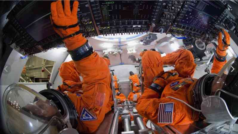
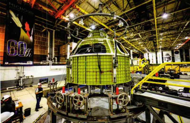
The Crew Module (CM) of the Orion spacecraft adopts a traditional design. It is a 57.5° truncated cone with a blunt spherical tail. It is mainly made of aluminum alloy and designed with a reusable concept. It has a diameter of 5.02 meters, a length of 3.3 meters, and a total weight of about 8.5 metric tons. It is produced by Lockheed Martin’s assembly plant in New Orleans. Its internal space is about 50% larger than that of the Apollo spacecraft, which can accommodate 4 to 6 astronauts and store various consumables and scientific research instruments. The crew module is the only part of the entire Orion spacecraft that returns to Earth after each mission (deceleration and landing by parachute). After landing and processing, the crew module can be reused. The docking port for docking with other spacecraft is also located on the crew module.
The features of the Orion spacecraft include a digital "glass cockpit" control system that is conceptually derived from modern aircraft, and a high-bandwidth, low-weight fiber optic system. In the past, American spacecraft (Gemini, Apollo and space shuttles) required manual piloting to dock with other spacecraft, but the Orion spacecraft is equipped with the same automatic docking system as the Progress, ATV cargo spacecraft and Dragon-2 manned spacecraft. It can use onboard sensors and computers to automatically dock with the International Space Station and prepare for astronauts or ground control centers to take over control in an emergency. In addition, all parts of the Orion spacecraft are designed to be modular as much as possible, which allows it to be continuously upgraded with new technologies from its first test flight in 2014 to its planned trip to Mars in 2030 and in its subsequent service life.
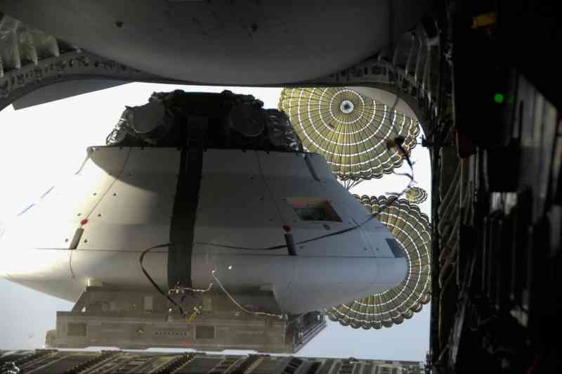
Before the crew module of the "Orion" spacecraft splashes down in the sea, it will encounter aerodynamic heating from the Earth’s atmosphere. Just like the "Apollo" command module encountered when it returned from the moon, or the space shuttle encountered when it returned from low-Earth orbit. Since the speed when returning from the moon is greater than that of returning from low-Earth orbit, the thermal protection of the crew module is a very significant design challenge. The thermal protection system of the crew module of the "Orion" spacecraft consists of a disposable thermal protection at the bottom of the crew module and reusable external and internal insulation materials. During the "Constellation" program, NASA evaluated a variety of candidate materials for the thermal protection system (for example: silica, carbon fiber, ceramics, and combinations of these materials). After extensive research, NASA selected Avcoat thermal protection and ablation-resistant materials for the Orion spacecraft crew module. Avcoat thermal protection and ablation-resistant materials are made of short-cut quartz fibers, epoxy-phenolic resin and phenolic hollow microspheres filled in honeycombs. It played an important role in the previous Apollo lunar mission, and similar materials were also used in the early space shuttles. Unlike the thermal protection system on the space shuttle, the heat shield of the Orion spacecraft will not be exposed during launch or in-orbit operation (it will only be exposed after separation from the service module), so it can be put into secondary use after landing with almost no inspection and maintenance.
The main landing mode of the crew module will be to land at sea near the west coast of the United States by parachute and inflatable water floating airbags, but emergency landing and recovery of the crew module will occur anywhere in the world. Current plans focus on performing an emergency landing on the ocean surface within 200 miles of the Navy’s San Clemente Island range, using a recovery ship equipped with a search and rescue helicopter and a rescue submersible developed at a cost-sharing agreement with the Navy and Military Sealift Command. After recovery, the various components of the crew module will be refurbished and reassembled. Components such as the escape system, service module and spacecraft adapter will be jettisoned at different points during flight, either disintegrating during reentry or splashing down in a remote location at sea.
Orion European Service Module (ESM)
In May 2011, the Director General of the European Space Agency (ESA) announced the possibility of cooperating with NASA to jointly develop a successor to the Automated Transfer Vehicle (ATV). On June 21 of the following year, Airbus Defense and Space announced that it had received two research projects worth 6.5 million euros to evaluate the possibility of using the technology and experience gained from the work related to the Automated Transfer Vehicle (ATV) and the Columbus laboratory module for future missions. In this research project, the possibility of using the service module together with the crew module of the Orion spacecraft was studied.
On November 21, 2012, the European Space Agency decided to develop a service module based on the Automatic Transfer Vehicle (ATV) for the Orion spacecraft, which will be produced by Airbus’s factory in Bremen, Germany. The following year, NASA announced that on January 16, 2013, the European Service Module (ESM) would be combined with the Orion spacecraft to carry out the Artemis 1 mission. In February 2016, various tests of the European Service Module were carried out at the Space Power Facility of NASA’s Glenn Research Center in Cleveland, Ohio. On February 16, 2017, Airbus and the European Space Agency signed a 200 million euro contract to produce a second European Service Module, which will be used for the first manned flight of the Orion spacecraft - the Artemis 2 mission. On October 26, 2018, the first European Service Module for the Artemis 1 mission was assembled at the Airbus Defence and Space plant in Bremen.
The European Service Module is approximately 4.1 meters in diameter and 4 meters in length and is made of an aluminum-lithium alloy. It mainly provides thrust for the orbital movement and attitude control of the "Orion" spacecraft; provides astronauts with water and oxygen for survival, and generates and stores electricity for the entire spacecraft to maintain the temperature of the entire spacecraft. It can also be used to transport non-pressurized cargo and scientific payloads.
The old plan for the "Orion" spacecraft used the circular UltraFlex solar panel design developed by ATK. On the European service module, four rectangular solar panels arranged in an X shape designed and produced by Airbus subsidiaries were used. The new solar panels can generate about 11 kilowatts of electricity, which is much higher than the old circular solar panels (4.6 kilowatts of electricity. The main engine used in the "Orion" spacecraft service module in the Artemis 1 to 3 missions (Mission 5 is tentative) is the orbital maneuvering system AJ10-190 engine left over from the space shuttle project. It uses a bipropellant of hydrazine 50/nitrogen tetroxide, developed by Aerojet-Rocketdyne. The adapter used to connect the European service module to the "Orion" crew module and the space launch system is produced by Lockheed Martin.
Compared with the command/service module of the Apollo spacecraft, the European Service Module has a weight reduction of about 40% when filled with propellant, with basically the same size (15,461 kg for the European Service Module and 24,520 kg for the Apollo); the power it can generate is about twice that of the latter (11.2 kW for the European Service Module and 6.3 kW for the Apollo). The habitable volume in the crew module has increased by about 45% (8.98 square meters for the European Service Module and 6.17 square meters for the Apollo), but the propellant loaded in the European Service Module for orbital maneuvers has been reduced by about 50% (8,600 kg for the European Service Module and 18,584 kg for the Apollo). The European Service Module can support four astronauts living in space for 21 days, while the Apollo spacecraft can support three astronauts for 14 days.
Launch Abort System (LAS) When an emergency occurs on the launch pad or during ascent of the Orion spacecraft, the Launch Abort System (LAS) will separate the crew module from the launch vehicle and eventually return to the ground. The system is essentially a smaller solid rocket motor and guidance control system installed on the top of the Orion crew module. It consists of an abort motor (AM) for accelerating the crew module, an attitude control motor (ACM), and a separation motor (JM) for separating the crew module from the launch escape system. This is a major safety improvement compared to the space shuttle design without an escape system. During a normal launch, the escape system will be separated and discarded approximately 30 seconds after the first stage separation, and will fall into the Atlantic Ocean. After the abort system is separated, the service module propulsion system provides escape energy for the crew
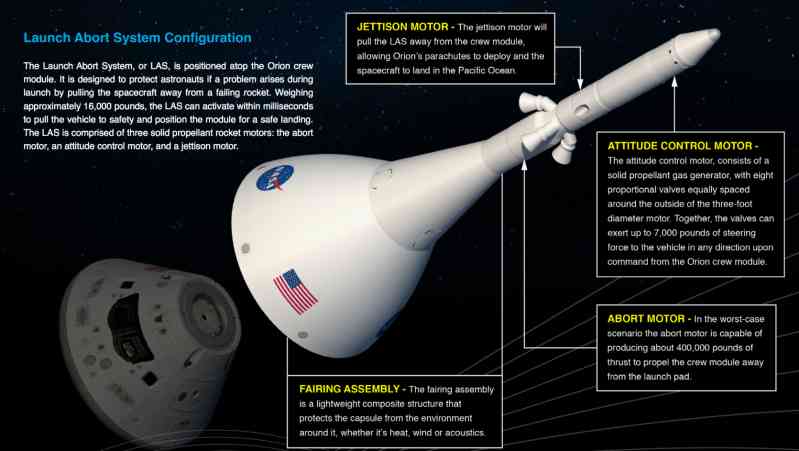
The system is designed to operate during the entire launch phase: from zero altitude and zero speed start (launch pad accident before launch), and the subsonic or supersonic phase of the ascent profile. That is, from the time the astronauts enter the crew capsule to the 120 seconds after the launch of the Space Launch System, before the booster separation at an altitude of 91 kilometers, if the rocket or other systems fail, the crew capsule of the "Orion" spacecraft will separate from the main body of the rocket through the engine of the launch escape system. Unlike the launch escape system of the "Apollo" spacecraft, the "Orion" spacecraft will use a pair of canards and the weight of the spacecraft itself to control and flip the crew capsule. After the launch escape system is activated, the "Orion" spacecraft will separate from the rocket as a whole and distance itself from the rocket through the AJ-10 main engine or the small attitude control engine (RCS) on the spacecraft. Once the crew capsule is out of danger, the escape system and the top assembly of the fairing will be discarded. Similar to the space shuttle’s "transatlantic emergency abort" procedure, the Orion spacecraft will fly under its own power, and the Orion crew capsule will use parachutes to land in western Spain or Morocco (when performing a lunar mission), or in Ireland or the United Kingdom (when performing an international space station mission). Only in extremely urgent and unexpected situations will a splashdown in the eastern Atlantic be adopted.
If the "Orion" spacecraft fails after entering orbit or the insertion into the orbit is not accurate enough to perform subsequent missions, it will be re-entered by the spacecraft’s own power. The crew cabin of "Orion" will land at Edwards Air Force Base on the west coast of the United States or in California, or at White Sands Spaceport in New Mexico.
Progress of the "Orion" spacecraft project
From its official naming in 2006 to 2020, the "Orion" spacecraft has cost a total of US$21.477 billion (converted to US dollars in 2020 based on the exchange rate), and in fiscal year 202, the "Orion" spacecraft also applied for 1.401 billion yuan in funding. NASA estimates that "Orion will cost an additional $140 million to $1.1 billion per year between 2021 and 2025."
Early stage testing
Between 2007 and 2011, NASA completed various environmental tests for the Orion spacecraft at the Glenn Research Center in Ohio. After the basic design of the Orion spacecraft was completed, Lockheed Martin and NASA began to build models of the Orion spacecraft for various tests. A full-scale model of the Orion crew capsule for astronaut simulation training was built in the Spacecraft Model Facility (SVMF) at the Johnson Space Center. The Langley Research Center also built a " The Orion model (BTA) is mainly used for splashdown tests. This model contains more than 150 sensors to collect test descent data. Various tests were conducted on this 8,200 kg model from July 2011 to January 6, 2012. The design rationality of each emergency rescue plan for the crew cabin was determined and evaluated. In addition, various unexpected situations that astronauts may encounter after landing were studied. The evaluation results show that the designed emergency rescue plans are reasonable in all aspects, including equipment, recovery ships and crew needs. Lockheed Martin’s Denver factory conducted vibration tests on the combination of the "Orion" spacecraft and the launch escape system.
The landing test model (Drop The U.S. Air Force’s C-17 strategic transport aircraft carried out a high-altitude drop test at the U.S. Army’s Yuma Proving Ground in Arizona. This test began in 2007, with the U.S. Air Force’s C-17 strategic transport aircraft carrying the "Orion" crew module model climbing to an altitude of 7,600 meters, and then opened the cargo door to drop the crew module model. However, failures occurred many times during the landing tests conducted in 2007, 2008 and 2010. The main problem occurred in the capsule parachute assembly system (CPAS) equipped with the "Orion" crew module. The parachute failed to open completely many times, causing the landing speed of the crew module model to be much higher than the designed maximum speed of 10 meters per second, which also required the test site to build more models for testing. In the test conducted on April 17, 2012 (the third crew module model was used this time), all the parachutes of the "Orion" crew module were working properly, and the model finally landed on the desert ground at a speed of 7.5 meters per second, becoming the first successful landing test.
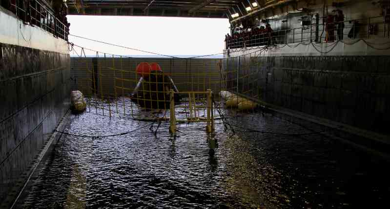
Before the first exploration flight test mission (EFT-1) in December 2014, the "Orion" crew module conducted several preliminary recovery tests. In August 2013, the US Navy dispatched the "San Antonio" class dock transport ship "Anchorage" to conduct a recovery test in a static state at sea in the protected waters of the Norfolk Naval Base. In this test, the feasibility of the recovery hardware and technology was fully verified. In 2014, two recovery tests were conducted under more realistic sea conditions to fully prepare for the crew module recovery mission of the first exploration flight test at the end of the same year.
Exploration Flight Test-1 (EFT-1/OFT-1)
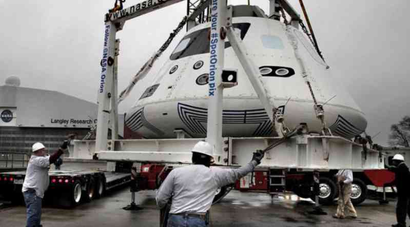
At 12:05 (UTC) on December 5, 2014, a Delta-4H rocket was launched from the SLC-37B launch pad at Cape Canaveral Air Force Base in Florida, carrying the Orion spacecraft crew module to perform the Exploration Flight Test-1 (EFT-1) mission. The purpose of this mission is to send the Orion spacecraft crew module into orbit to test the reliability of its separation system, launch escape system, avionics, thermal insulation performance, flight control system, landing and recovery system.
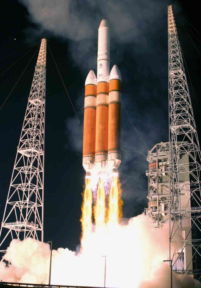
The Orion spacecraft crew module for Exploration Flight Test-1 was manufactured by Lockheed Martin at its factory in New Orleans, Louisiana. After the manufacturing work was completed, the crew module was sent to the Kennedy Space Center for subsequent assembly and testing. The Delta-4H rocket that undertook this mission landed on the launch pad on October 1, 2014, and combined with the Orion spacecraft crew module on November 11. In Exploration Flight Test-1, the Orion crew module flew in orbit for a total of about four and a half hours, with an orbital apogee altitude of about 5,800 kilometers, which made the re-entry speed of the Orion crew module reach 8,900 meters per second, exposing the crew module to high temperatures of about 2,200 degrees Celsius.
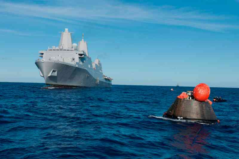
The crew module of the Orion spacecraft splashed down in the Pacific Ocean (23.61°N114.46°W) about 1,030 kilometers southeast of San Diego at 16:29 (UTC) on December 5, 2014. It was recovered by recovery personnel sent by the USS Anchorage dock landing ship and then brought back to the Kennedy Space Center for subsequent testing and evaluation. After completing the relevant work, the crew module was exhibited at the Kennedy Space Center.
Ascent Abort Test-2 (AA-2)
The primary purpose of Ascent Abort Test-2 (AA-2) was to demonstrate and validate the Orion spacecraft’s Launch Abort System (LAS) using a custom-built Orion Abort Test Booster (ATB), a Peacekeeper (LGM-118) ballistic missile first stage purchased from the U.S. Air Force and modified by Orbital ATK and Northrop Grumman. The test flight took place on July 2, 2019 at 07:00 (EST)/11:00 (UTC) with the ATB taking off from Cape Canaveral SLC-46. The LAS was activated approximately 55 seconds after the ATB took off, when it reached an altitude of 9,400 meters and near the point of maximum dynamic pressure. It was monitored via telemetry and 12 data recorders. In this test, the launch escape system performed very well, laying a good foundation for the first flight mission of the Artemis program in 2022. (To be continued)