Lifting body
The lifting body is an unconventional aerodynamic layout. It does not have ordinary wings, but uses a wing-body fusion to generate lift in order to obtain a higher lift-to-drag ratio at low speeds. The concept of the lifting body was originally discovered by NASA by chance when studying ballistic missile reentry technology, and then applied to the design of returning spacecraft. At first glance, a pure lifting body looks like a stone, but this stone can generate lift and fly.
In traditional aircraft design, the fuselage is used to carry loads and the wings are used to generate lift. They are two independent parts. It’s like a model airplane made by a child, with a ruler tied to a stick.
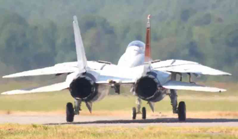
The third-generation aircraft introduced the concept of wing-body fusion during design. The fuselage and wing have a smooth transition through curves, which not only reduces aerodynamic drag but also increases the fuselage volume. Both the F-14 and Su-27 are typical integrated lift body designs. The rear fuselage is part of the wing, wide and flat, and the longitudinal section is wing-shaped, which can generate partial lift. The engine adopts the form of underwing nacelles, arranged at large intervals. The tunnel formed between the two engines can constrain the airflow, increase the pressure on the lower surface, and improve lift. When the wing sweep angle of the F-14 is 20°, the fuselage lift accounts for 40% of the total lift; when the wing sweep angle is 68°, the fuselage lift accounts for 60% of the total lift, which is amazingly efficient. However, the third-generation aircraft is not a true lift body. It only adopts a partial lift body design in the rear fuselage. Due to the times, stealth and supersonic maneuverability are not considered at all.
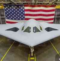
In order to achieve the unity of stealth, supersonic cruise and super maneuverability, most of the fifth-generation aircraft adopt a supersonic lifting body design. The entire fuselage starts from the diamond-shaped nose, and the upper and lower surfaces are smooth and large-curvature continuous surfaces, with an integrated fuselage and wing design. The outward-inclined lower side of the diamond-shaped nose can generate lift and pre-compress the airflow flowing to the air inlet. The longitudinal section of the fuselage is similar to the airfoil, and the configuration is very clean, which is conducive to the diffraction of radar waves and makes the entire fuselage an ideal lifting body to generate additional lift.
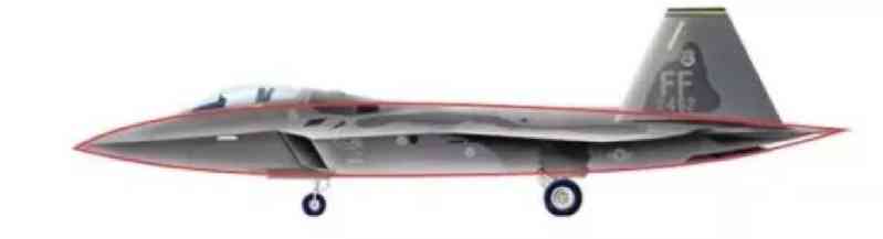
Thanks to the flat dual-vector nozzle at the tail, the F-22 lifting body design is the most perfect.
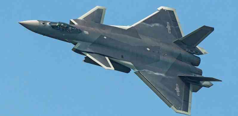
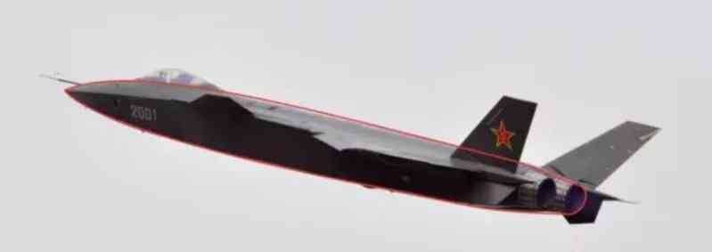
J-20 ranks second, the only drawback is that the tail engine uses a traditional three-way nozzle, which cannot be narrowed, resulting in a large induced drag.
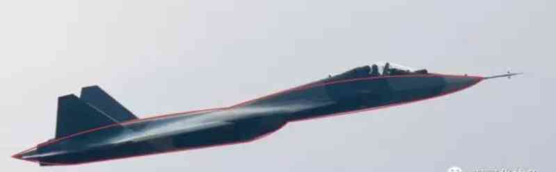
T-50 inherits the aerodynamic layout of Su-27, and has the most conservative design. The raised front fuselage and the suspended engine nacelle both destroy the continuity of the fuselage surface, which is far behind the trend.
From this perspective, relying on deep aerodynamic theory, supercomputers and large-scale supersonic wind tunnel systems, only the United States and China can design supersonic lifting body fighters.
Frameless integral canopy
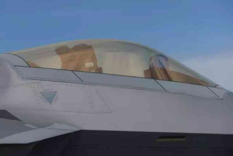
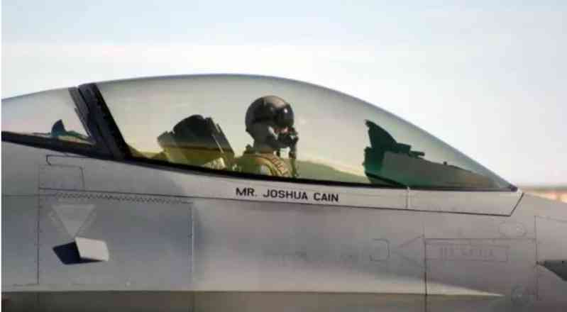
J-20 is the first aircraft outside the United States to use a frameless integral canopy. The frameless canopy eliminates the front partition frame. The entire canopy is like a drop of water, presenting a nearly 360-degree unobstructed field of view, which is very beneficial for air situation perception and close-range combat. However, the difficulty of making a frameless canopy is also very high. Before this, only the F-16 and F-22 used it among the fighters put into production around the world.
The canopy of a modern fighter is not as simple as ordinary bulletproof glass. It must simultaneously meet many almost contradictory and demanding conditions, such as high light transmittance (advanced ones can reach 90%), small optical distortion (caused by curved surfaces), strong anti-collision performance (no penetration by a four-pound bird strike), high strength (part of the entire fuselage), light weight, and good temperature resistance (when flying at Mach 2, the external temperature of the canopy can reach 110°; in a high-altitude low-temperature environment, it must have electric heating, defogging, and deicing functions). For the fifth-generation aircraft, stealth performance must also be added.
Take the F-22 as an example. Its canopy uses two polymers: acrylic esters with better environmental adaptability as the inner and outer layers, and polycarbonate with poor weather resistance as the middle layer, so that the advantages of the two different materials complement each other. The traditional multi-layer plexiglass structure uses pressure molding, which presses layers together. The whole process takes up to six weeks. The F-22 canopy is produced by the British GKN Aerospace Company and adopts a new injection molding method, which only takes one hour. Injection molding of a single type of organic material is a very common process, but injection molding of two different materials can also have clear layers, uniform quality and sufficient strength. This is extremely difficult. The cost of a F-22 canopy is as high as 286,000 US dollars.
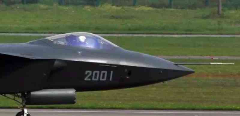
The first two verification aircraft of the J-20 adopted the same full frameless integral canopy as the F-22. As soon as they appeared, they attracted a lot of applause and were considered to have reached the world’s advanced level. Starting from the 2011 prototype, there was an additional reinforcement frame at the front of the canopy, which attracted a lot of discussion. Some said that the quality of the full frameless canopy was not up to standard and had to be reinforced; some said that it was reduced to save money and weight. In fact, it is just the opposite, but I think this change is a normal improvement.
The canopy of the F-22 has a considerable defect. In order to meet the strength requirements, the frameless design makes it 20 mm thick and weighs 360 pounds. Because it is too thick and difficult to penetrate the canopy, the traditional canopy ejection technology can only be used, that is, the canopy must be thrown away with a rocket before ejection, and then the seat is ejected. In the case of the fifth-generation aircraft pursuing supersonic maneuvers, the time window for ejection and rescue in distress is getting smaller and smaller, and any delay may lead to ejection failure. The F-22 has crashed and the pilot was killed because of a canopy failure that prevented the pilot from ejecting successfully. The famous canopy sawing incident at Langley Air Force Base in 2006 demonstrated the severity of this defect.
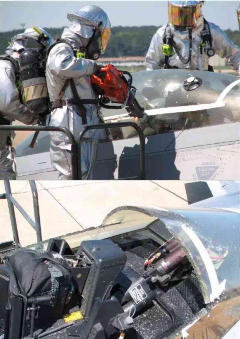
To use an integral canopy to improve the field of vision and ensure the success rate of ejection, the best solution is to use a non-delayed canopy ejection method, install a blasting cord on the top of the canopy, and detonate a small equivalent charge at the same time as the ejection, destroying the integrity of the canopy, relying on the collision angle on the top of the seat to directly penetrate the canopy, shortening the reaction time and increasing the success rate of rescue. Of course, canopy ejection itself is not a new technology. British aircraft prefer this method and have been using it for decades, but they all have frame structures.
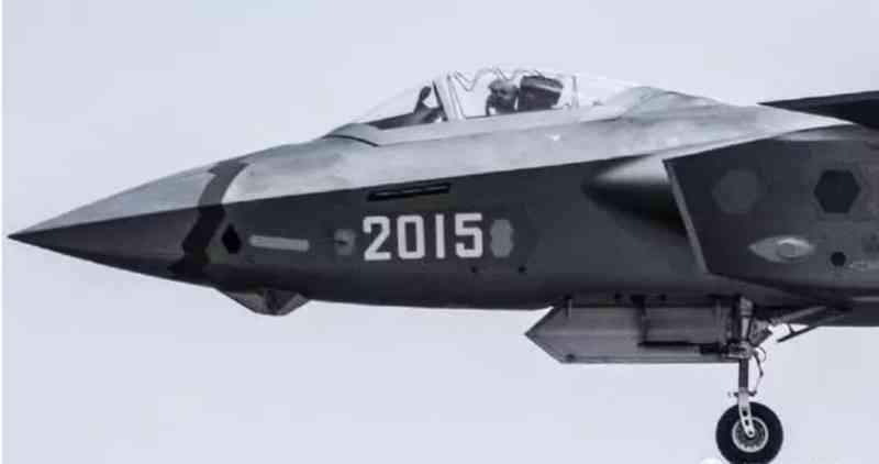
The United States has adopted a variable thickness canopy design since the F-35, adding a reinforcement frame to the integrated canopy. The windshield area in front of the frame is thicker to ensure strength and anti-collision capability; the thickness of the area behind the frame is thinner, which is conducive to ejection through the canopy. This reinforcement frame is located inside the canopy, and the outer surface is still a continuous plexiglass surface. There is no seam on the surface of the traditional partition frame, which does not affect the stealth. This technology not only reduces weight, but also reduces manufacturing difficulty and prolongs service life, killing two birds with one stone. The J-20 is the second fighter in the world to use this technology.
The canopy design of the J-20 is very pragmatic, perfectly combining supersonic ejection life-saving capability and stealth, reaching the world’s most advanced level.
DSI inlet
DSI inlet means "supersonic inlet without boundary layer separation". It is a new inlet concept developed by Lockheed Martin in ten years. It was tested on the F-16 and officially used on the X-35 verification aircraft in 2000.
To explain DSI clearly, we must first talk about what the boundary layer is. When the aircraft flies at high speed, the air close to the surface of the fuselage rubs against the skin. Because of the viscosity of the air, the flow rate is reduced, and turbulence is easily generated, and the flow rate and direction become unstable. The air layer where the flow field changes from the beginning of the flow rate to the surface of the fuselage is called the boundary layer.
If such a slow-moving and undisciplined boundary layer is sucked into the air intake, it will affect the engine’s air intake efficiency. In serious cases, it will cause the engine blades to stall or surge, damage the engine and even shut down. The higher the speed, the thicker the boundary layer, and the greater the impact. Therefore, since the first generation of jet fighters, aircraft designers have been racking their brains to eliminate the influence of the boundary layer and allow only clean air to enter the air intake smoothly.
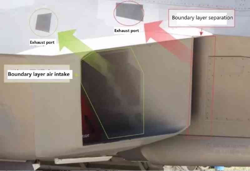
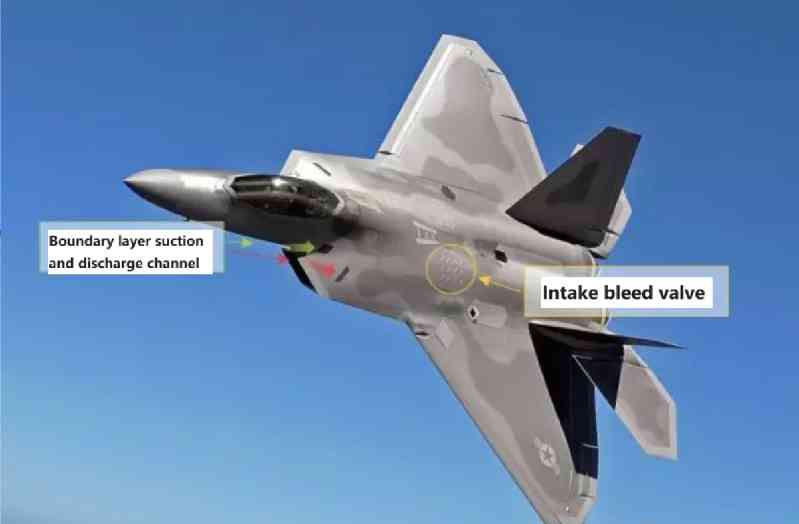
The traditional method is to use boundary layer partitions/separators to separate and release the boundary layer from the clean airflow, and then use suction measures to suck away the boundary layer on the surface of the inlet. Before the birth of DSI, the most advanced inlet design in the world was the F-22’s Garrett inlet, scientifically known as the double-bevel waverider inlet, which uses the shock wave generated by the prism-shaped nose to decelerate and pressurize the airflow entering the inlet, thereby eliminating the complex inlet adjustment system like the F-14 and F-15, and at the same time has better stealth performance.
But the F-22’s fixed inlet is optimized for a cruising speed of Mach 1.6. When it exceeds this speed range, the intake efficiency decreases and must be adjusted with a huge bleed valve. At the same time, it also has a very complex boundary layer isolation and intake and exhaust bypass system. The boundary layer partition forms a large cavity, which is very unfavorable for frontal stealth. Both the boundary layer air intake and exhaust ports need to be treated with stealth, which increases the structural weight, reduces the available space in the aircraft, and increases resistance.
DSI air intake replaces all boundary layer isolation and air intake and exhaust systems with a three-dimensional bulge. As a compression surface, there is a pressure gradient difference between the top and the periphery of the bulge. When the boundary layer flows through the bulge, the high-pressure area on the top of the bulge pushes the boundary layer away from the bulge and flows to the low-pressure area around the bulge. With the carefully designed forward-swept air intake lip, the boundary layer is discharged from the appropriate positions on both sides of the air intake.
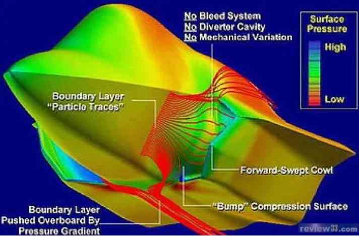
DSI has no moving parts, nor does it have a heavy and complex isolation/intake and exhaust system, which greatly reduces the structural weight and the corresponding maintenance. It has a small frontal area, low resistance, and good stealth against inlet shielding. It has a high total pressure recovery coefficient, a wide speed adaptation range, and an intake efficiency that is at least as good as the Garrett inlet, or even better. According to Lockheed Martin research and calculations, the use of DSI can reduce weight by more than 300 pounds, which is a very considerable weight reduction effect for fighters that are very careful about weight. Moreover, a 1% increase in the total pressure recovery coefficient of the inlet can increase the engine thrust by 1.3% to 1.5%. When the available engine thrust is insufficient, the optimization of the inlet design is of great significance.
The principle looks simple, but the technical difficulty of DSI is very high. The size, shape, and position of this fixed bulge must take into account the intake efficiency under all speed ranges and elevation changes, which reflects the highest level of computational fluid dynamics. It requires a large number of high-speed wind tunnel tests and extremely high manufacturing precision. Metal materials cannot meet the processing requirements and can only be made of composite materials. So far, only the F-35 has adopted the DSI technology in Western countries. The T-50, which was launched nearly 20 years later than the F-22, still uses the Russian-style Garrett air intake, indicating that Russia has not mastered this technology. The quasi-fourth-generation aircraft such as the "Shinshin" being developed by Japan, South Korea, Sweden and other countries have not touched on the DSI technology at all, and the aerodynamic design is more than a level lower.
After tracking and learning from Lockheed Martin’s technical concepts, China developed its own technology and first adopted the DSI air intake on the Xiaolong 04 aircraft in 2006. Since then, it has been unstoppable and quickly popularized this top technology to all subsequent fighter designs. Not only the mid-range J-10B, high-end J-20 and J-31, but also the lowest-end JL9 "Mountain Eagle" trainer aircraft modified from the J-7 have adopted DSI. There are belly intake, side intake, stealth, and simple ones. Chengdu Aircraft Corporation, Shenyang Aircraft Corporation, and Guizhou Aircraft Corporation are all using them, which shows that China has thoroughly mastered this technology.
FC-1
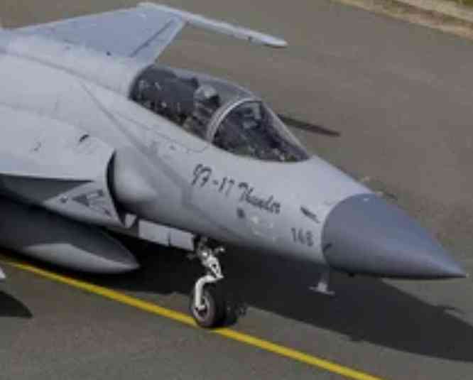
J-10
J-31
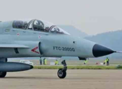
JL-9
Details of the DSI air intakes of four Chinese fighters. As an aside, no matter what high technology is mastered by the Chinese, with China’s all-encompassing industrial categories and huge output, this technology will soon become popular and become profitable.
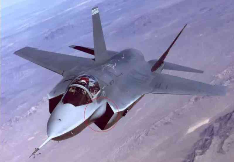
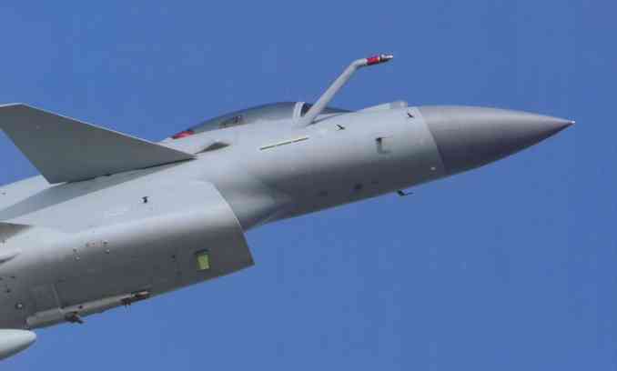
The J-20 is the third fighter designed by China’s Chengdu Aircraft Industry Group (abbreviated as Chengfei) to use DSI. In a sense, Chengfei’s DSI implementation experience exceeds Lockheed Martin and is the best in the world. All previous DSI air intakes, including the F-35, have bulges located in the center of the air intake, and the left and right shapes are symmetrical. The J-20’s bulge is asymmetrical, located higher, and the front end is sharper than any other DSI bulge, with better high-speed performance and, of course, more complex aerodynamic design.
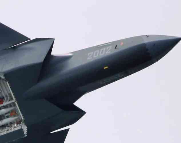
From Xiaolong to F-35, the DSI air intake gives people the feeling that the high-speed performance is poor. The analysis article claims that the J-20’s air intake adopts an adjustable side wall design, or the upper lip can droop like the F-15 to meet the intake requirements of different speeds. Some people even speculate that the bulge itself is flexible and can produce flexible deformation under air pressure. So far, all the pictures on the Internet have not taken close-up photos of the details of the J-20’s air intake, and it is impossible to judge whether adjustable parts are used. As can be seen from the figure below, the bulge and the lip of the air intake side wall of the J-20 are made of composite materials different from the metal skin of the fuselage, and the color is lighter, similar to the color of the radar cover. However, it is too arbitrary to judge that these two parts can move or deform based on this.
A 2005 public paper on the J-10B prototype inlet by Nanjing University of Aeronautics and Astronautics in China showed that the total pressure recovery coefficient of its fixed DSI inlet was better than that of the F-4D with a traditional two-dimensional three-wave inlet at Mach 1.8-2.0, and only slightly lower than that of the F-15 with a two-dimensional four-wave inlet. Now that so many years have passed, there is reason to believe that the J-20’s fixed DSI inlet is sufficient to adapt to a wide range from subsonic to twice the speed of sound. The bulge and lip are made of composite materials. In addition to the manufacturing process requirements, the main reason is to use wave-absorbing or wave-transmitting materials for stealth.
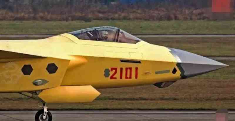
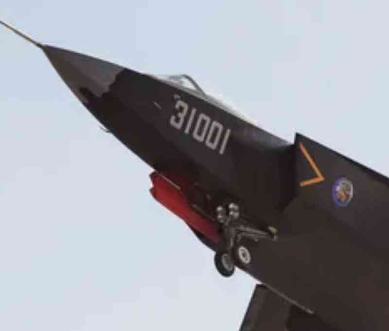
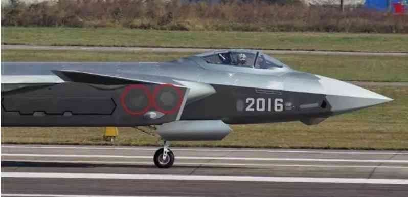
The two red circles in the picture below are two hexagonal windows with small honeycomb-shaped openings on the surface. Judging from the position and size, they are the intake/exhaust valves of the air intake duct, which are used to adjust the intake volume under different speed conditions. Compared with the two huge exhaust valves on the back of the F-22, these two openings are much smaller and closer to the air intake duct. The bypass duct takes up less space and has high intake and exhaust efficiency.
The DSI air intake of the J-20 reduces the structural weight, enhances the stealth performance, and reduces the windward resistance while ensuring the intake efficiency. I have spent so much time and effort on DSI to illustrate that the air intake system of the J-20 is the most advanced among the fighter jets known in the world.